![]()
Please note:
V H cam systems are now EOL (End of Life)
and are replaced with the new VisTrak system.
 -
-
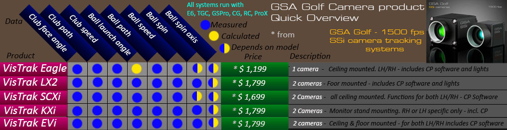
Click above image to see the VisTrak systems

V and H cam calibration
Note: This page is for V and H cam calibration

Click the above image to read about stereo calibration
Verifying your current camera calibration

Click the above button to read about how to verify your current camera setup calibration
![]()

 -
-
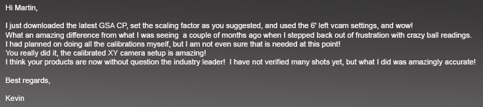
Above, a customer e-mail from 04/21/2017 regarding the new extended calibration
![]()
Factory calibration table set
All current GSA Golf Control Panel versions and updates now include a factory set camera extended calibration table
that will be used if users choose not to calibrate the cameras themselves.
see the end of this page for factory calibration details or click the above image
XY camera setup calibration
Why is calibration or correction required?

With the classic XY camera setup, the Hcam is mounted on the ceiling looking straight down to see the direction of the ball left and right (as shown in the above image)
Two methods of correction
The two methods of correction are:
1. Full calibration from a pre-defined or user defined calibration table
2. A user defined percentage correction
Full calibration
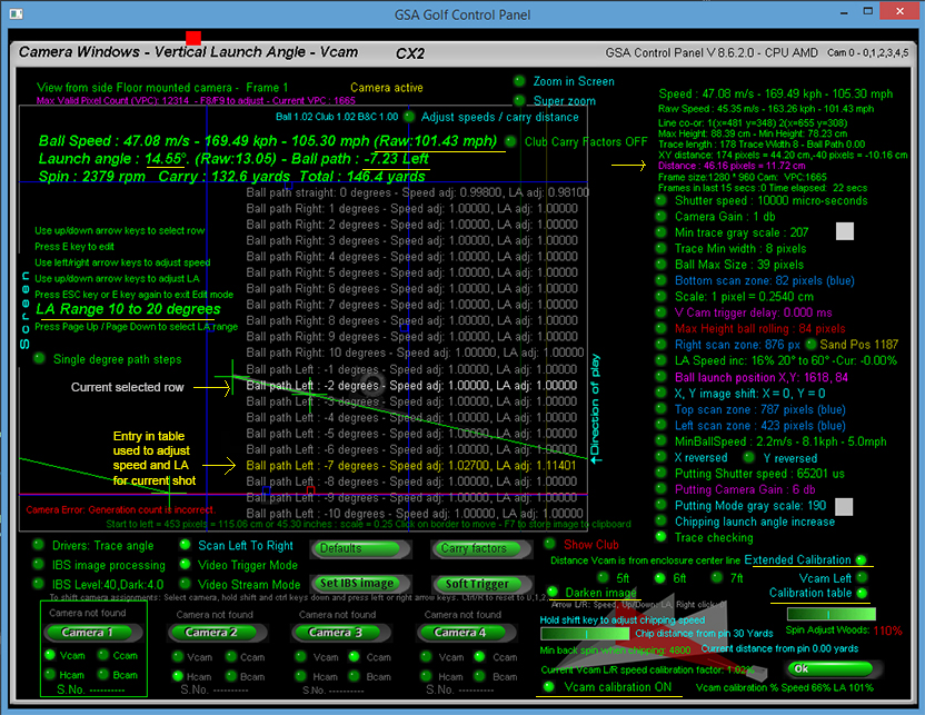
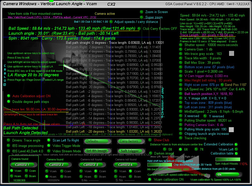
Viewing and editing the calibration tables
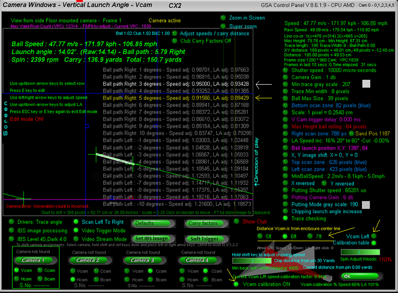
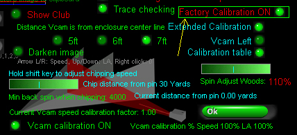
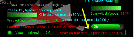
Click the "Calibration table" option ON to view and edit the calibration tables
The yellow row shows the speed and LA adjustment made for the current shot
In the above example the ball speed was reduced to 91.566% of it's original speed and the LA reduced to 89.429% of it's original LA
The calibration is reducing (instead if increasing) both the speed and LA as the ball path is right - towards the camera - and thus the ball traces will appear larger.
The white row is the row selected by the edit cursor (Use up/down arrow keys to move).
Note that there are 3 sets of tables depending on the distance the Vcam is from the enclosure center line (i.e. 5 ,6 or 7ft)
Also note that the tables are reversed if the Vcam camera is mounted on the left side of the enclosure (Vcam left option ON)
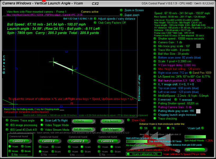
To use this method of correction, switch the Vcam calibration ON in the Vcam window
Note that you can adjust the amount of calibration too
In the above example, speed calibration is reduced to 66% and LA calibration to 101%
Also note that the correct distance the Vcam is from the enclosure center line should be set
In the above example the distance is set to 7ft
In addition, ensure that if the Vcam camera is mounted on the left side of the enclosure, that the Vcam Left option is set to ON
Extended XY calibration
The new XY extended calibration expands this calibration to a 40 degree range (+/- 20 degrees)
for 6 launch vertical angle ranges of 10, 20, 30, 40, 50 and 60 degrees.
See the end of this page to read more about Extended Calibration
User defined percentage correction
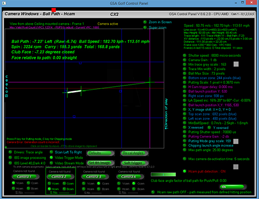
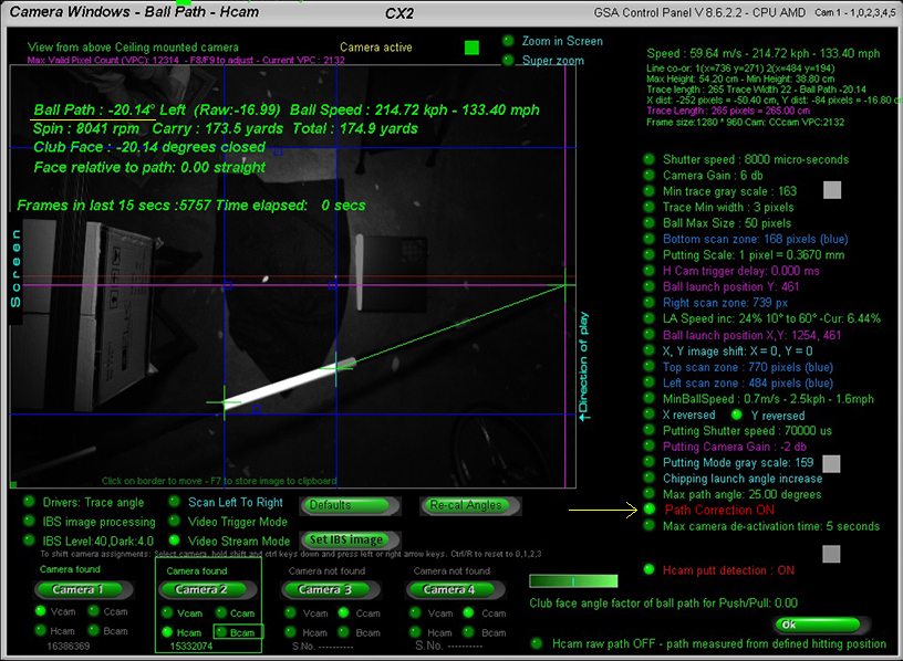
Hcam path correction
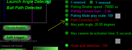
To-date all calibration and linear adjustments where made for the Vcam camera which is responsible for ball speed and vertical launch angle calculations.
However, the Hcam ball path camera also requires either calibration or linear adjustment in order to calculate true ball path angles.
Calibration tests showed that the Hcam will only detect true ball path angles when the ball vertical launch angle is below 20 degrees.
As the vertical launch angle increases, the ball is getting nearer to the Hcam ceiling mounted camera and lens perspective distortions start to kick in.
Some examples are:
With a true ball path angle of 10 degrees left or right, the Hcam measured path without calibration was:
LA 20 degrees - path angle : 12 degrees
LA 30 degrees - path angle : 15 degrees
LA 40 degrees - path angle : 20 degrees
With a true ball path angle of 20 degrees left or right , the Hcam measured path without calibration was:
LA 20 degrees - path angle : 24 degrees
LA 30 degrees - path angle : 28 degrees
LA 40 degrees - path angle : 40 degrees
As can be seen, high lofted shots can result in ball paths being measured twice as much as they really are. i.e. a real path angle of 20 degrees, is measured as 40 degrees left or right without correction.
To correct this there's a new "Path correction" option in the Hcam window that linearly adjusts the path to it's correct value depending on the vertical launch of the ball.
An Hcam calibration table will be available shortly too
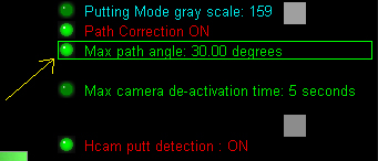
BTW, if you have noticed that some high lofted shots weren't being detected, then it was probably due to the ball path being measured by the Hcam exceeded the "Max ball path" setting in the Hcam window.
Without path correction it would be very easy for the ball path to exceed the limit setting with high lofted shots and then the launch would be declared as invalid.
Other adjustments
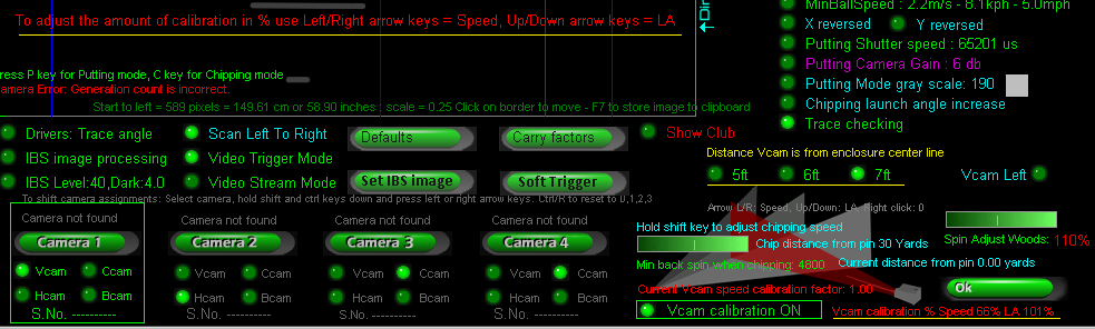
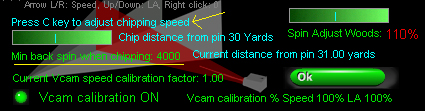
Chip speed
Chip distance
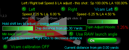
To set the chip distance, hover the mouse cursor over the "Chip distance from pin" text and use left and right mouse clicks adjust the distance.
In the above example the distance to the pin where the chipping mode will be automatically activated is set to 30 yards.
"Min back spin when chipping"
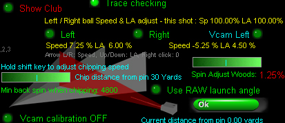
Another major factor when chipping is the measured or calculated back spin
In order to prevent the ball from rolling straight off the green when chipping, the back spin should be quite high.
Use the slider bar to set the "Min back spin when chipping" to at least 4000 rpm
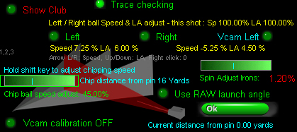
"Spin rate adjustments"
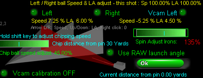
When not using our ball spin cameras, spin rates are calculated from club and ball launch data
Use the spin adjust slider bar to increase or decrease the calculated spin rates.
In the above example, calculated spin rate for all irons has been increased by 135%
Note that spin rate adjustment settings are separate for irons and woods. Hold the shift key down to select irons, otherwise woods are selected.
Hcam path correction
Some small tweeks were made to the Hcam path correction today and the new 7ft calibration table was made with Hcam correction ON.
5ft and 6ft tables didn't use the Hcam correction so will be redone mext week. In the meantime use the 7ft table even if your Vcam is closer or further away.
Chipping mode
When in Chipping Mode, the "min backspin when chipping" slider bar turns into .... "chip ball speed adjust"
and "Launch Angle inc" turns into "Chipping launch angle inc"
Note "Launch Angle inc" is not required when using "Extended Calibration".
"Launch angle ball speed adjustments"
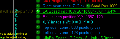

Just click multiple times on the new "Launch angle increase" option to set the LA increment to be 0, 5, 10, 15, 20,25, 30 or 40%
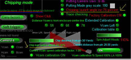
Scaling factor
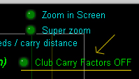
Individual club carry factors
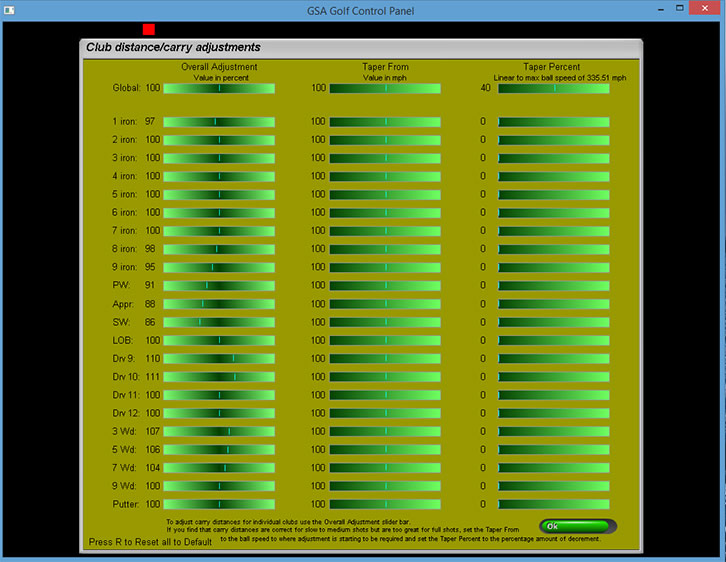
You can also add speed / carry factors for each club separately in this window
Click the "Carry Factors" button in the CP's Setup window to access this carry factors window.
Note that the "Carry Factors" option has to be set ON in order for them to take effect
There's also a "Driver boost" factor in the Setup window that just adjusts ball speeds for Drivers
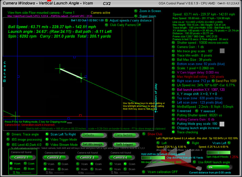
Adjust carry and spin directly in the Vcam window
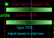
There's a new slider bar in the Vcam window that allows users to adjust the LA based carry and spin factors directly in the Vcam window and thus see the results of carry adjustment immediately.
New speed & spin adjustments based on launch angles as well as club types
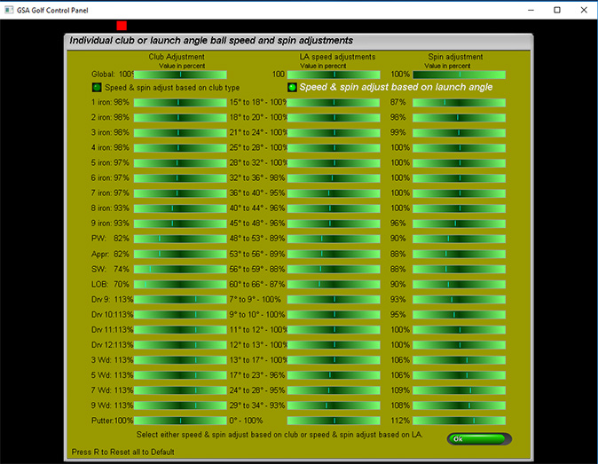
In addition to the carry & spin factors based on the club being used, there is now a carry (ball speed) factor and spin rate factor based on ball launch angles.
This should be more accurate than the club based method as it cannot be what the launch angle is based on the club selection.
Note that these carry and spin factors are either club or LA based and not both together. If "Carry factors" are switched OFF then neither will be used.
The third column in the window is used to set spin rate factors for specific clubs or launch angles. Again, if "Carry factors" are switched OFF then these spin factors will not be used.
Also note that the standard LA speed increase or decrease is still active in the Vcam window when selecting carry factors ON.
Click the above image and scroll down to Q 16 to read more about standard LA speed adjustments.
V and H cam
126 step extended XY Calibration
for V and H cam camera setups
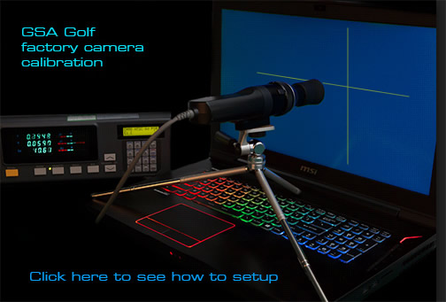
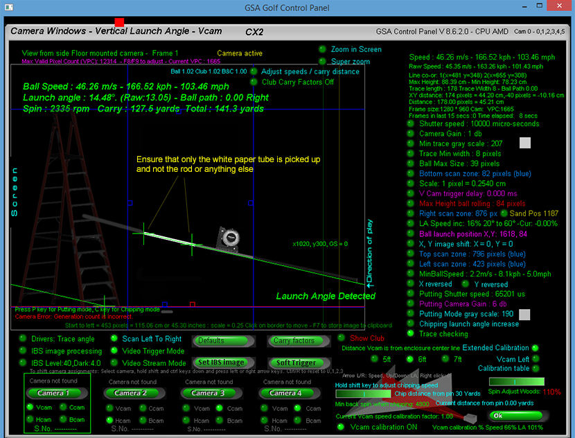
The calibration method here is to use a white tube of a known length on a pole that represents a ball trace at a constant speed which is then placed at various vertical and horizontal angles.
The object of the calibration is to ensure that the length of the trace (i.e. white tube) remains constant at all angles and the launch angle remains constant for the particular tilt of the pole as measured by an inclination meter
Note that there is a standard factory set extended calibration for XY camera setups but if you'd like calibrate your system yourself then this is how
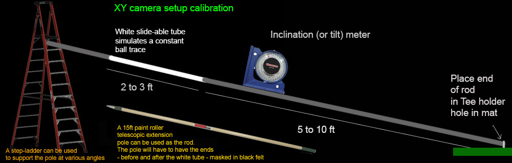
The V and Hcam calibration method involves using a black or dark long rod with a movable white plastic tube or paper roll attached to one end
and pinned down at the other end with a swivel mounted on a base plate at the usual ball hitting position on the hitting mat.
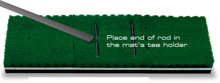
Place the end of the rod in the hitting mat's tee holder hole.
This represents the ball's initial position on the ground.
The rod is tilted upwards in 10 degree steps from 10 degrees to 60 degrees to simulate various launch angles of the ball
and moved both left and right in 2 degree steps to simulate ball path from 20 degrees left to 20 degrees right.
The total number of entries is then 21 x 6 = 126
A tilt meter is used to measure the real angle of the rod and the Hcam is used to measure the ball path.
Slide the white tube up or down as necessary to keep it in the same FOV of the camera with every step. This simulates the same trigger point.
With each step, capture new V and H cam images of the rod by pressing the Enter key.
Pressing the Enter key on your PC's keyboard sends "Soft trigger" instructions to both the V and H cams.
Use blocks of some kind (e.g. step ladder, stools or chairs etc) to support the end of the rod to get the desired vertical angles.
Use the Hcam to check the desired ball path
Ensure that the "Ball Launch Position" has been set correctly in the Hcam window.
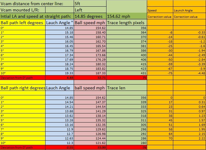
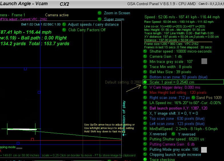
Start at Vertical angle of 0 degrees and zero degree path and set the scaling factor so that the distance measured in the Vcam is the same as the actual length of the white part of the rod
In the above case, the white tube is 50 cm long and the length measured by the camera in pixels is 197 px
The scaling factor is then set to a value that converts the length measured in pixels to 50cm. In this case: 0.254
and LA speed inc / dec is set to zero percent
as these adjustments will no longer be required after calibration
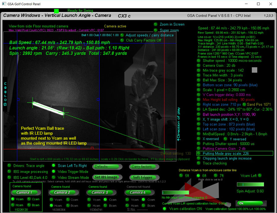
Note that there are a number of new features in the Vcam window.
1. Raw speed is now shown. Raw speed is the speed calculated from the camera without any adjustments or calibration
2. A Darken image option is now available that darkens the Vcam image so thet the calibration table is more readable.
3. Calculated trace length distance is now shown in a pink shade so that it stands out more
Auto calibration
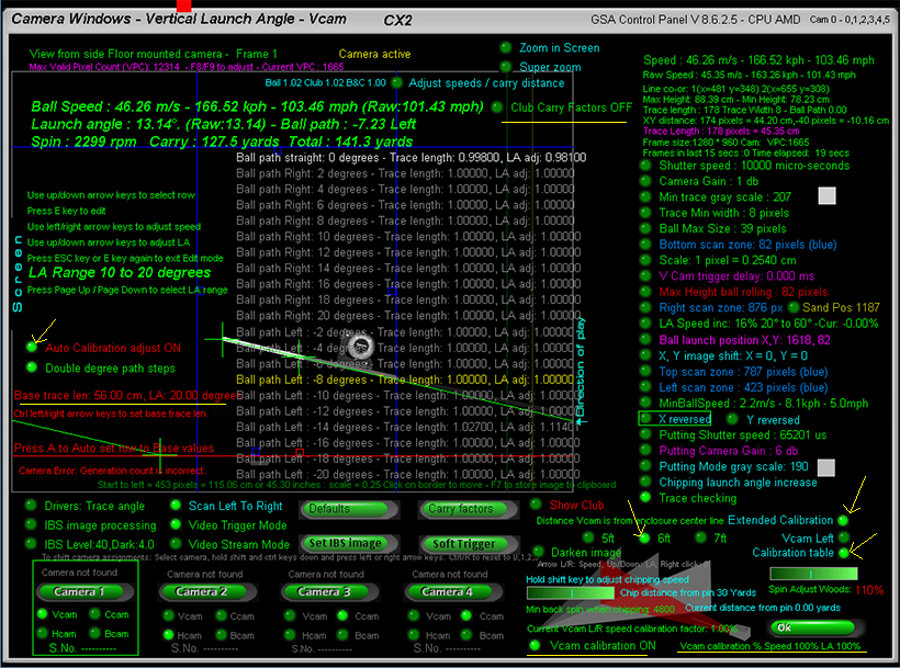
Calibration Example
Here the Hcam is being used to measure the ball path angle during the calibration process
Note that Hcam "ball path correction" has to be switched ON in order to use the Hcam to measure ball paths accurately
If not using the Hcam to measure the path of the pole then a plum line
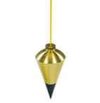
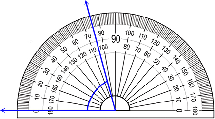
suspended from the pole beginning over a large protractor will have to be used to measurre exact pole paths
Calibration process tips
Factory calibration table set
All current GSA Golf Control Panel versions and updates now include a factory set camera calibration table
that negates any user requirement to calibrate the cameras themselves.
The table consists of 3 calibration tables each consisting of 126 entries
for various distances the Vcam is from the center line
Vcam distances from the center line are 5ft, 6ft and 7ft.
Note that the calibration table "calibLRex.csv" is placed in the "C:\Program Files (x86)\GSAControlPanel\data" folder when you download the latest CP update.
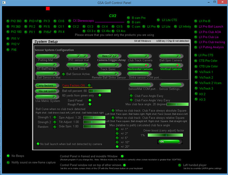
In order to use it, the new "Factory Calibration" option must be on.
Any user calibration tables won't be overwritten when this option is on but if you would like to edit the factory tables then switch the "Factory Calibration" option OFF again before editing.
The table will then be automatically saved to the "C:Users\Public" folder.
Calibration factors used now displayed
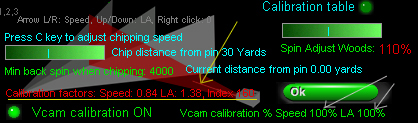
The calibration factors used for the current shot are now displayed in the Vcam window.
These are Speed adjustment, Launch Angle (LA) adjustment and the index number into the calibration table.
In the above example, the raw speed of the ball was reduced to 84% and the raw LA increased by 38%
Extended calibration "Scale" factor = 0.2780
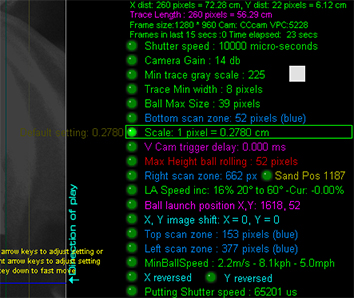
Note that the Scale factor for the calibration tables was set to 1 pixel = 0.2780.
This scale factor used with the calibration tables should result in exact ball speed measurements across the entire 0 - 60 degree launch angle and +/- 20 degree path range.
Increasing or decreasing this scale will result in decreased or increased measured ball speed across the entire range should you care to change it.
Don't forget !
If your Vcam is mounted on the left side of the enclosure, ensure that the "Vcam Left" option is ON
otherwise your calibration will be reversed
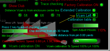
Also don't forget to set the distance your Vcam is from the enclosure center line
Currently distances are 5ft, 6ft and 7 ft.
If your Vcam is over 7 ft away from the center line then just use 7ft setting for now.
Other distances will be available later this year
Also don't forget to set the amount of calibration to 100% for both speed and LA to start with
Later you can reduce or increase the amount of clibration for both Speed and LA to suit
In the above example the speed calibration was reduced to 50% so that any ball speed adjustments for ball hit left or right will be 50% less
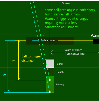
Note that the calibration tables where made with a ball to trigger distance of 5ft.
Later next month we'll have exact speed calibration percentages for various other ball to trigger distances
Also don't forget to set "Extended Calibration" ON and "Factory calibration" ON
Note that these are default ON with the new CP releases
And finally, don't forget to switch "Carry factors" OFF
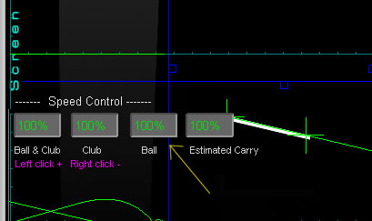
and "Ball speed controls" to their default of 100%
![]()

![]()

 Home
Home Simulators
 Cameras
 Software
 Enclosures
 GSA Courses
 E6 Courses
 Business
 Tech News