![]()


Need support ?
![]()


![]()
Technical Help

![]()

Read this first
![]()
 -
- -
-


![]()

 --
-- -
-
 -
-
 -
-  -
- 
 --
-- -
-
 -
- -
-
- -
- -
-
 -
- -
-


![]()
GSA Golf system minimum PC requirements

Intel i5 or above Processor
8GB RAM Nvidia 1070 Graphics Card or equivalent
(Dedicated GPU with DirectX 11 Support)
25GB of Hard Drive Space
Windows 10 (Required)
Internet Connection (Required)
When using VisTrak systems - Native USB3 ports (Required)
( i.e. no add-on PCie USB3 adapters for PCs that don't come with USB 3 ports as standard )
![]()
VisTrak problem solving.
Click the below button to find solutions to common VisTrak user issues

Click above to read about the CX and VisTrak Stereo setup
![]()
![]()


Please check the above to see video setup instructions
Cameras not registered?
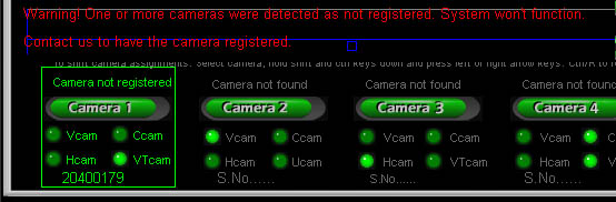
Cameras are registered in the Control Panel's executable program.
If you see the above message stating that the cameras are not registered,
then download and run the latest CP update from the tech news page.
![]()
Non SSI
Camera Installation Q & A
CTS & PX2 Q & A are further down this page
![]()
Q 0
Q 0: The cameras are connected to the PC but the Control Panel states "No cameras detected"
A: The cause of this is most probably that the camera drivers haven't been installed or if they were, then the "USB Pro" option wasn't de-selected.
Go to the "Auto method of installing the camera drivers" on the camera installation page here
see below for a repeat of these instructions
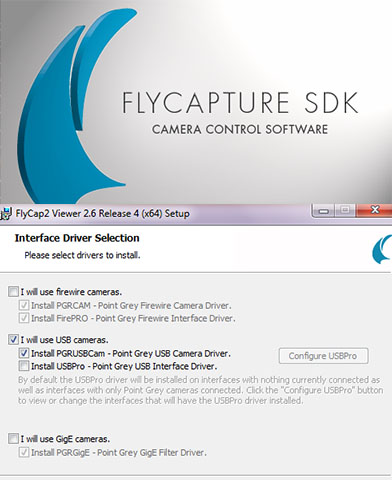
The above SDK installation program FlyCapture_2_4_3_11_x86 is located on the supplied DVD and must be started before any cameras are connected.
All camera drivers are now installed automatically with this new Camera Control Software
Select "I will use USB cameras" and select "Install PGRUSBCam driver" when prompted.
Do not select the "USBPro" option !
If you have previously run this install program and think you may have selected the USBPro option then you must uninstall the SDK and re-run it
Other possible causes of this issue:
After down loading and installing a new CP version that overwrites a much older CP version
the "Fixed Assigns" option in the Vcam window was set ON.
To Fix: Switch the "Fixed Assigns" option OFF, exit and restart the CP.
Once the cameras have been re-assigned to their corresponding function (i.e. Vcam, Hcam, Ccam, Bcam etc)
you can switch the "Fixed Assigns" back ON again so that they will always appear in the CP in the correct order.
![]()
Q 1
Q 1a : The cameras are connected to the PC but I don't see any images
Q 1b: The cameras are connected to the PC but the CP states "No cameras detected"
Q 1c: The cameras are connected to the PC but the CP cameras window states "Camera not found"
A: Check the following
1. Are the camera drivers installed?
Go to the "Auto method of installing the camera drivers" on the camera installation page here
2. Are the cameras detected in the "Cameras" window of the Control Panel (CP) ?
You should see the message "Camera found" above each camera button in the Cameras window of the CP
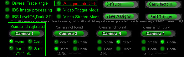
If not, then switch "Assignments OFF" in the Cameras window in the Vcam window of the CP and restart the CP
If you see "Camera not registered" then send us the camera serial number as displayed in the CP in an email
3. When you select the "Video Stream Mode" do you then see new images ?
If yes then the cameras are running okay so the fault is with the camera trigger from the SX line scan camera
4. Are the cameras really connected to the PC via the USB cables?
Each camera must be individually connected to the PC via it's own USB cable
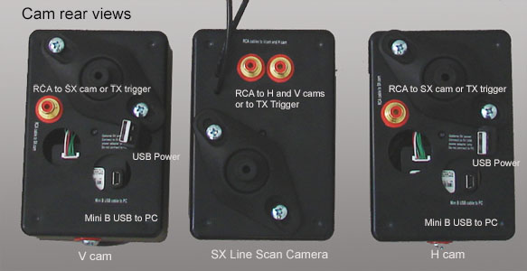
Note: there are two USB connectors on the back of the V, H , C cams. One is a mini B connector and the other a standard B connector.
The smaller mini B connector is the camera data connector and must be connected to a USB port on the PC.
The larger standard USB B connector is just for additional power and should be connected to a USB power adapter.
5. Are the USB cables to the cameras too long?
USB cable specs state that the maximum length of a USB cable between hubs is 3 meters or 10 feet
To fix: use either powered USB hubs for every 10ft of USB cable or USB over Cat adapters.
To test if it's the cable lengths causing the problem, connect each camera to the PC using just the supplied 6ft USB mini B cable.
If you then see that all cameras are running and images are being grabbed when set to "Video Stream Mode" in the CP cameras window,
try connecting one of the supplied 9ft USB extension cables to the camera using a powered USB in between the 9ft cable and the 6ft cable.
If the cameras are still running okay and you require more USB cable length, add a second 9ft extension cable to the 6ft cable so that there is a 15ft (9 + 6) length of USB cable going from the powered USB hub to the camera
and a 9ft extension going from the USB hub to the PC.
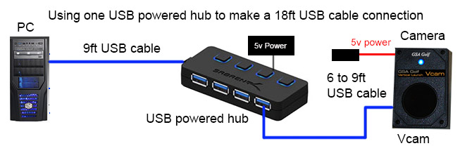
Note that then the 15ft length exceeds the maximum safe length of a USB cable without hubs so if the camera is then no longer functioning correctly
then a second powered USB hub will have to be added to the cable 6ft - to - 9ft USB connection.
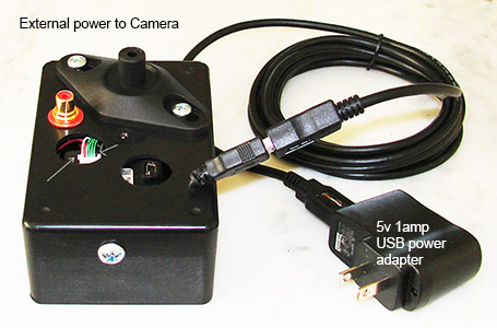
Note that using cable lengths over 15ft will probably require that the camera be externally powered with a 5v power source
as will multiple cameras connected to one PC. i.e. each camera will require external 5v power
6. Are the cameras connected to a separate internal hub and bus on the PC ?
Often times USB ports on the PC will share the same internal hub and bus on the PC's mother board
Go to "How to determine what USB ports are sharing a USB bus or hub on your PC" on the Camera installation page to read more
Connecting multiple cameras to ports that share one USB Host Controller will split the USB 2 480MBit/s speed.
e.g. 4 cameras on one controller will then only run at 480/4 = 120MBits/s and probably won't function
Connecting multiple cameras to the same USB Hub on the PC's mother board will split the max hub's output of 2.5 watt power
Power - in this case - will be shared to the cameras connected to it and this will cause the cameras to not function as each camera requires 2.0 watts to function.
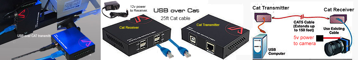
USB over Cat cable extender - up to 150ft
An alternative to running USB cables over long distances with powered USB hubs every 9ft, is to use Cat5 cables with a USB over Cat unit at either end.
![]()
Q 2
Q 2: What does "Camera Engine Start Error" mean?
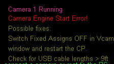
If you see this message displayed on the main window of the CP then communication with the camera has failed. i.e. trigger instructions can't be sent etc.
If the message appears during play then it is usually due to the cable lengths being too long and the camera has insufficient power.
Fix 1: Ensure that the cables connecting the camera to the PC has a powered USB hub at the halfway mark.
i.e. if using 2 9ft usb cables for a total length of 18ft, then there should be a powered in the middle.
Fix 2: Add an additional 5v USB power adapter to the camera
Note: all new GSA Golf cameras have an additional USB power plug on the back of the camera.
Contact us if your camera doesn't feature this power plug.
If the message appears immediately when starting the CP and you have added new cameras, it is probably the fixed assignments causing it.
Switch "Fixed Assigns OFF" in the Vcam window of the CP and restart the CP.
Check that the camera functions assignments are correct (i.e. that camera 1 is the Vcam, camera 2 is the Hcam etc) and click the Save Assigns button and switch "Fixed Assigns" back ON.
![]()
Q 3
Q 3 - 1: I see new images when in "Video stream mode" but not when the cameras are triggered by the SX line scan camera
A: Check the following
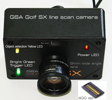
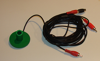
1. Are the two RCA cables connected from the SX camera to the Vcam and Hcam cameras ?
2. When you turn the SX sensitivity dial on the remote control first all the way right (clockwise) and then left (anti clockwise), does the green LED light on the SX cam turn on?
3. Is the ceiling mounted IR LED lamp on?
The LEDs in the lamp will glow a dark red when on. Note that there's a photocell on the LED lamps that automatically switch the lamp off when ambient light is in the room.
To prevent this, stick a small piece of black electrical tape over the photocell
Q 3 - 2: My cameras are connected and detected but no new images are captured when triggered
even though the sx line scan camera's green light lights up when striking a ball
Q 3 - 3: My cameras are connected and detected but no new images are captured when they are set to video mode.
Q 3 - 4: My cameras are connected and detected but I have to put the cameras in video mode for a moment before they will grab new images when triggered
A: There are 3 possible causes of this issue
1. The cable lengths are too long - Ensure that the cable has a single powered USB hub in the cable chain.
2. The cameraa has insufficient power. - Connect an additional USB power adpater to the camera.
3. The cameras are running on the same USB channel in the PC
Try connecting the USB cables from the camera to different ports on the PC
If that doesn't help, install a new USB adapter card to the PC and connect only one camera to it leaving the other camera connected to a USB port on the PC
![]()
Note: Connecting cameras to the standard PC USB ports
If not using separate USB cards - i.e. you're connecting cameras direct to the PC USB ports -
connect one camera to a USB port at the front of the PC and the other(s) to a port (or ports) on the back of the PC.
This ensures that at least two cameras are running on separate USB channels
![]()
Q 4
Q 4: My cameras only trigger with high lofted shots
A: This will occur when the SX camera's sensitivity is not set high enough or when the camera is mounted too high.
To set the sensitivity, first turn the dial all the way right( clockwise) and slowly turn the dial left until the green light comes on and then turn very slowly back until the green light just goes off again.
Note: do not stand under the SX cam when doing this otherwise your body will cause IR light reflections to get back into the camera. Stand as far away from the SX camera as possible
Ensure that the SX camera is not mounted too high. The max recommended mounting height is 9ft.
Q: I've set the SX sensitivity as high as possible but it will still only detect high lofted shots
A: This will occur when the SX camera's sensitivity cannot be set high enough due to the underlying surface reflecting too much light
Are you using a non or low reflective black carpet or turf under the SX camera?
We have lower reflective padded turf carpet now should you prefer not to use black carpet
If you can't set the SX line scan camera's sensitivity high enough to detect low shots or putts then use an additional floor mounted trigger array

Click the above image to read more about trigger arrays.
![]()
Q 5
Q 5 : My cameras are all running but seem to be in the wrong order.
i.e. camera 1 is the Hcam and camera 2 is the Vcam
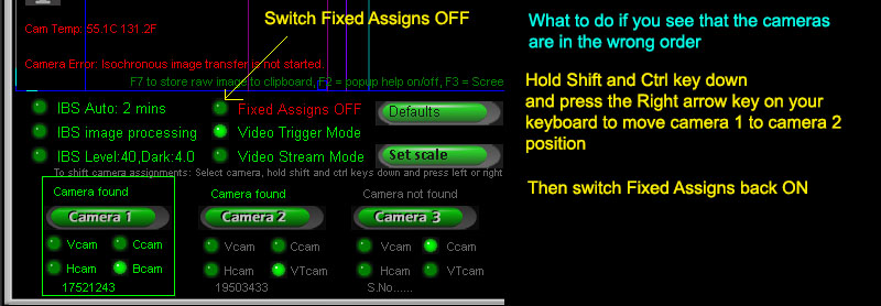
A: This due to incorrect camera assignment
The correct assignments are Camera 1 = Vcam, Cam 2 = Hcam, Cam 3 = CTS frame 1 and Cam 4 = CTS frame 2
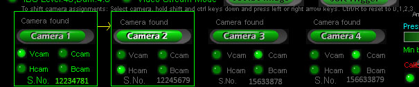
To change the camera assignments
select the camera in the CP cameras window, hold both the shift and ctrl keys down, and press the left or right arrow keys to move the camera up or down the sequence.
Press the "Soft Trigger" button to grab a new image and confirm that it is the correct camera assignment
If you're using the latest CP version V 8.6.4.9 or greater, switch the camera fixed "Assignments" OFF to start with and restart the CP.
Once the correct camera assignments are made you can save them by clicking on the "Save Assigns" button in the Vcam window.
Camera Assignments
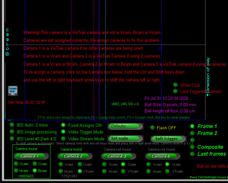
If you see the above warning message in the camera windows, then the camera assignments are not correct.
With the VisTrak IRVC, camera 1 is the ball launch angle camera and camera 2 is the VisTrak camera.
Follow the above instructions to re-assign the cameras to their correct positions.
White Screen
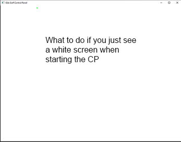
If the camera assignments aren't correct, then the CP may hang and just show a white screen when started.
To fix:
1. unplug all cameras from the PC.
2. restart the CP and switch the "Fixed Assigns" option OFF.
3. shut the CP down.
4. plug the cameras back into the PC and restart the CP.
5. Check that assignments are correct.
If it's a 2 camera system, then camera 1 is the Vcam camera and 2 is the VisTrak camera.
If it's a 3 camera system, then camera 1 is the Vcam camera, camera 2 the Hcam camera and 3 is the VisTrak camera.
If re-assigning cameras then the "Fixed Assigns" should be switched back ON again and the CP re-started
![]()
Q 6
Q 6 : When I re-start the PC, the camera's order changes
i.e. camera 1 is the Hcam and camera 2 is the Vcam etc
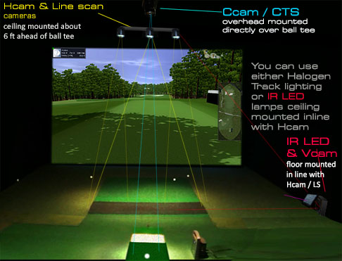
The control panel is designed to see the cameras in the following sequence
Camera 1 is the Vcam (The floor mounted Vertical ball launch camera in a CX2 to CX6 system)
Camera 2 is the Hcam (The ceiling mounted horizontal ball path camera in a CX2 to CX6 system)
Camera 3 is the Ccam (The ceiling mounted club tracking camera - frame 1 in a CX3 to CX6 system)
Camera 4 is the Ccam (The ceiling mounted club tracking camera - frame 2 in a CX4 to CX6 system)
Camera 5 (bank 2) is the Bcam ball spin camera - frame 1 (floor mounted in a CX6 system)
Camera 6 (bank 2) is the Bcam ball spin camera - frame 2 (floor mounted in a CX6 system)
To identify which camera is which you can click the "Soft Trigger" button to grab a new image or set the camera to "Video Stream Mode".
From the images you should be able to see what camera was being triggered.
If you find that cameras are not being assigned in the correct order then you can manually re-assign the cameras.
To do this, select the camera in the CP cameras window, hold both the shift and ctrl keys down, and press the left or right arrow keys to move the camera up or down the sequence.
Note that color cameras - as used in the CTS club tracking systems - will appear in monochrome if not correctly assigned. i.e. if a color CTS camera appears as camera 1 in the control panel then the images will show in monochrome instead of color. CTS color cameras must always be assigned to camera positions 3 or 4.
If you're using the latest CP version V 8.6.4.9 or greater, switch the camera fixed "Assignments" OFF to start with and restart the CP.
Once the correct camera assignments are made you can save them by clicking on the "Save Assigns" button in the Vcam window.
![]()
Q 7
Q 7 : Why are my Vcam and/or Hcam images upside down or back-to-front ?
A: This usually due to incorrect mounting orientation but you can easily flip the images
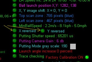
If the image appears up side down, click the "Y reverse" option on the right hand side of the window
If the image appears back-to-front, click the "X reverse" option
![]()
Q 8
Q 8 : When I hit a shot nothing happens and no ball is launched in the software
A: Check the following
1. Is the SX Line scan camera triggering the V and H cameras and grabing new images when the cameras are in the default "Trigger" mode?
To test, walk under the SX line scan camera ensuring that you see that the green LED goes ON as you stand under the camera.
You should see that the V and H cameras capture new images (of yourself in this case).
When you strike a ball you should see that the bright green LED lights up for a second or two.
If not then click the above image go to the Line Scan camera setup page.
If using a trigger array, ensure that the green LED light on the trigger array is OFF and only lights up when a shadow is cast over the array.
Click the above image to read more about trigger arrays.
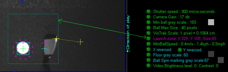
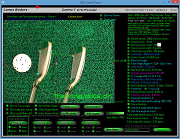
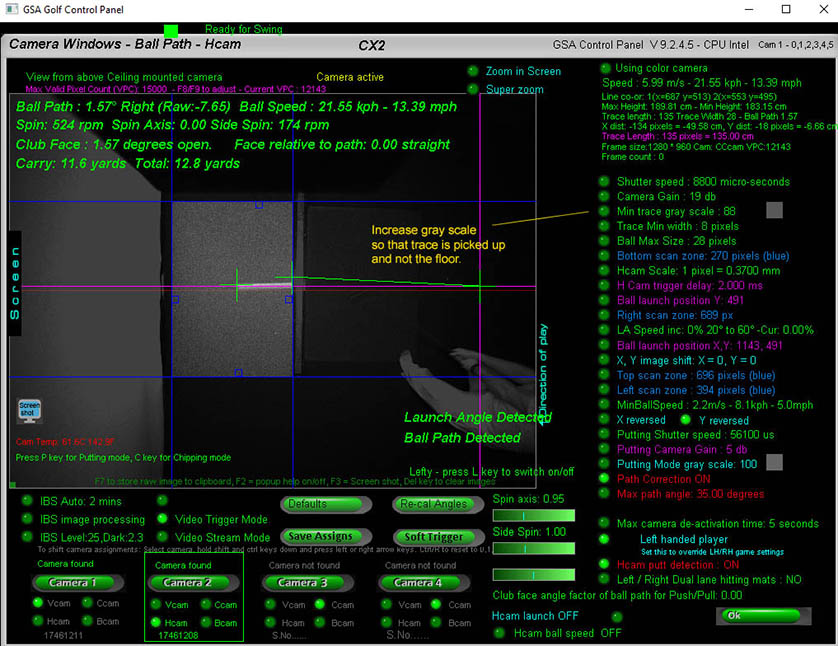
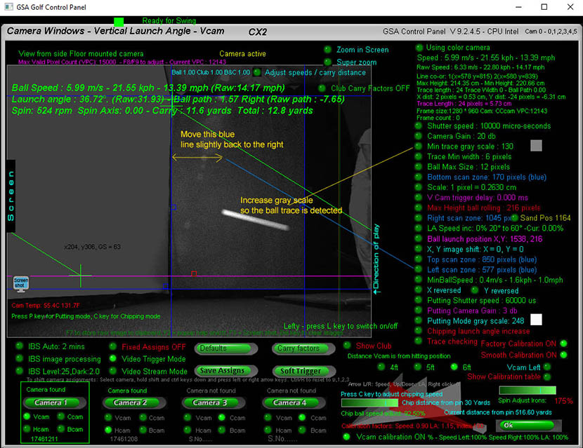
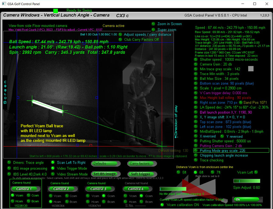
2. Check the Vcam and Hcam images to see if the ball trace has both the green cross hairs on it at both ends
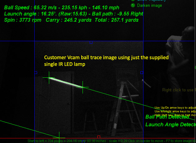
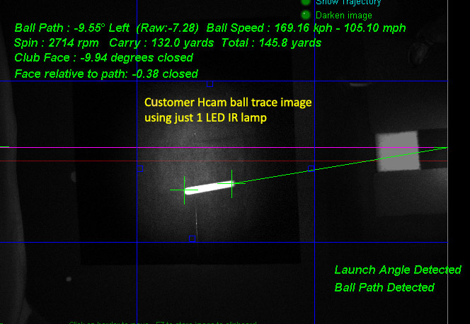
Your V and H cam images should look similar to the above images with the two green cross hairs at both ends of the ball trace

Ensure that no other bright objects in the valid FOV of the cameras are being picked up as in the above image
3. Check the Max path angle and max camera de-activation time in the Hcam window
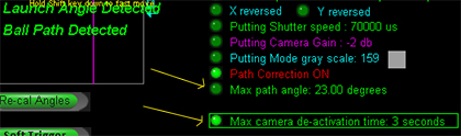
If the ball path (left or right) of a shot was greater than the "Max path angle" then the shot will be declared invalid and the ball won't launch in the software
After a shot, the cameras are de-activated for a few seconds to prevent the following club or player from re-triggering the cameras.
If you play a ball during this de-activation period then the cameras won't capture the ball and the ball won't launch in the software.
The de-activation time can be user set from 2 to 8 seconds.
3. Check that you have selected the correct game software you are using in the CP's main window


In the case of TGC, ensure that the TGC server is running and you see the message "TGC connected" in the CP
4. Check that the CP is detecting the shot
Testing shot detection
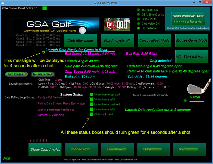
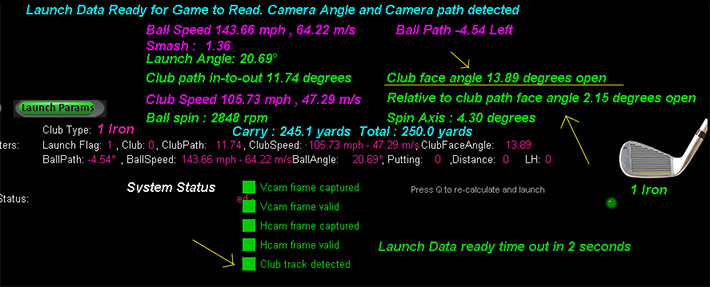
Using just the Control Panel (CP) , valid shot detection is displayed in the CP's main window with a text message displaying "Launch Dada Ready for Game to Read" as shown in the above image.
This aqua colored text message will be displayed for around 4 seconds after a valid shot has been detected.
In addition, all System Status indicators in the CP's main window will momentarily turn bright green as shown in the above image.
If you see that any of these indicators do don't turn green after a shot then further investigation of the camera images is required to determine the cause.
5. Check that the CP is detecting the ball trace
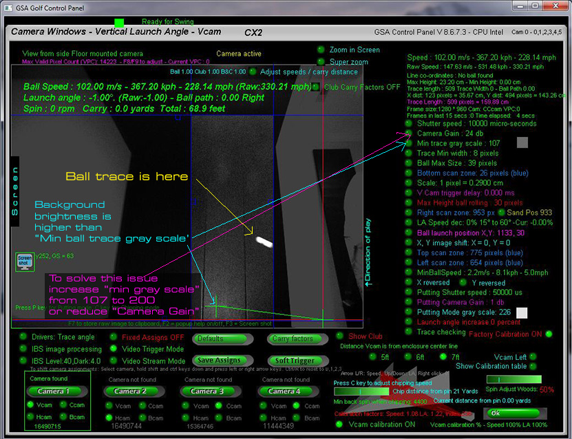
In the above Vcam shot image the background contains pixels brighter than the "Min Trace Gray Scale"
6. Check that all cameras are still sending data
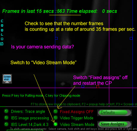
If cables are too long or there is an issue with the PC, a camera can go "off-line"
To check: go to all cameras in the Control Panel - one after the other - and click the "Video Stream Mode" button.
You should see that the camera is sending new images at a rate of around 35 frames per second.
7. Are the IR LED lights actually ON ?
You should see that the LEDs in the lamps glow a dark red if they are ON.
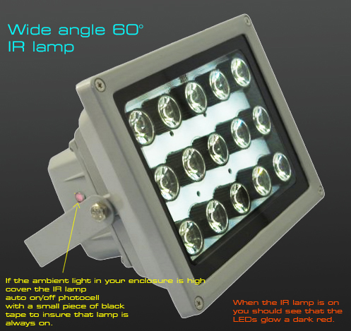
Ensure that the LED lights are ON
The IR LEDs in the lamp will glow a drak red when the lamp is ON
If plugged in and you don't see the LEDs glow red, place a piece of black electrical tape over the photocell on the side of the lamp.
![]()
Q 9
Q 9 : After playing a while a camera will stop working
A: This is usually due to the USB cable length being too long
USB cable specs state that the maximum length of a USB cable between hubs is 3 meters or 10 feet
It's possible that the cameras will function with longer cables for a while but connections may become unstable.
With the GSA Golf camera system it is usually the Hcam camera that is effected by this as the cable to this camera is the longest
To fix: use powered USB hubs for every 10ft of USB cable and power the cameras with external 5v power supplies.
Note: Do not connect more than one camera to each USB hub!
Other than SX line scan cameras, each camera will require it's own individual USB powered hub
Go to the USB camera cables section on the Camera installation page or click the above "Wiring and Cables" button to read more
![]()
Q 10
Q 10 : I can only get 2 out 3 cameras or 3 out of 4 cameras to work
A: 1. This is usually due to the USB cable length to cameras being too long and/or cameras are connected to a single USB bus on the PC
USB cable specs state that the maximum length of a USB cable between hubs is 3 meters or 10 feet
To fix: use powered USB hubs for every 9ft of USB cable or use CAT5 cables with a powered USB over CAT adapter.
Note that the cameras will probably rrequire external power when using long USB or CAT5 cables
USB over Cat cable extender - up to 50ft
An alternative to running USB cables over long distances with powered USB hubs every 9ft, is to use Cat5 cables with a USB over Cat unit at either end and supply the camera with external 5v power.
To fix: use powered USB hubs for every 10ft of USB cable and power the cameras with external 5v power supplies.
A: 2. Each camera shoulb be connected to a separate internal hub and bus on the PC
Often times USB ports on the PC will share the same internal hub and bus on the PC's mother board
Go to "How to determine what USB ports are sharing a USB bus or hub on your PC" on the Camera installation page to read more

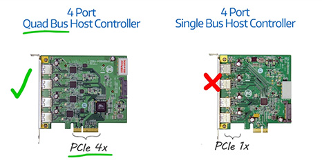
A: 3. Your PC's mother board is shutting down power to the internal USB bus when the overall power consumption exceeds a certain threshold
Usually adding an extra USB multi-port controller card to the PC will fix this problem
If it's just one extra camera that is not working then a lower priced single channel card will probably suffice, otherwise you'd require a multi dedicated channel USB card
Go to the USB ports section on the Camera installation page to read more
A: 4. Use multiple PCs if your PC won't function with more than 2 cameras
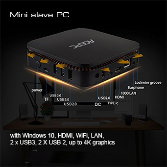
Note that Slave PCs don't have to be high end gaming PCs
We've tested and found that a basic mini PC for just $199 functions just fine as a slave PC
![]()
Q 10 b c
Q 10b : I can get one but not two cameras to trigger with the line scan camera
Q 10c : I can get two but not three cameras to trigger with the line scan camera
A1: do the following test to see that the cause is not a too long wiring issue or a SX line scan camera issue
Connect two or all cameras to the PC directly with just the short 6ft USB cable to the PC.
Check to see that both cameras grab new images when clicking the "Soft Trigger" button in both the V and H cam windows.
If not, then disconnect the RCA trigger cables from the SX line scan camera for the cameras and try again.
If this works, then check the RCA cables from the line scan camera and check that the green light on the SX line scan camera goes ON when an object passes under this camera.
If the green light on the SX camera is permanently ON or does not come ON at all then check the sensitivity of the SX line scan camera.
Instructions for this are on this page:
If you find that all cameras trigger well with the short cables but not with the long cables then there is a cable issue.
see for possible solutions
A2: Cameras are connected to ports using the same USB channel
If you find that the cameras grab new images when "soft" triggering them individually but only one camera grabs a new image when triggered by the line scan camera,
then this indicates that bot cameras are connected to ports sharing the just one USB channel.
To fix: ensure that one camera is connected to a USB port on the back of the PC and the other to a port on the front of the PC.
Usually the back USB ports on the back and the front of the PC run on separate USB channels.
If this doesn't fix the problem or you are using more than two cameras then an extra USB card should be installed on the PC's mother board in either the X1 or X2 expansion slots.
![]()
Q 11
Q 11: How can I hit fades and draws with the CX2 system ?

A: Click the above button to read how to do this
![]()
Q 12
Q 12 : How can I hit fades and draws with the PX5 system ?
A: Your PX5 system will automatically detect fades and draws (plus slices and hooks) based on the relative club face angle to club path
Ensure that after a shot that the system actually detected club data. Check the CP's main window for valid club data.
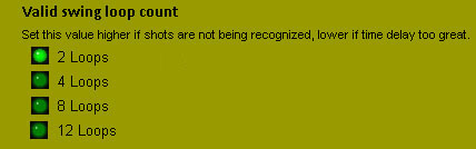
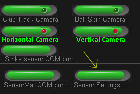
If not, then check that the "Valid swing loop count" in the "Sensor Settings" is set to 2 loops.
The "Sensor Settings" window is accessed via the "Setup" windows
![]()
Note to PX5 users:
Ensure that you are using the latest CP update. Below is a quote from the Tech News page om Jan 7 2018
January 7 2018
Fix: PX5 - Ball track cameras not waiting long enough for club data to come in with fast shots
PX5 users may have noticed that with slow shots the club track data from the sensor mat is being used while with fast shots club data is being calculated from ball data and the real club data from the sensor mat is being ignored.
This is now fixed in this version of the CP. i.e. the system will wait a second or so for the incoming data from the mat - which is slower to come in than data from the cameras.
Fix: PX2 / PX5 club tracking sensor mat - measured club face angle being reduced with increasing club speed
I'm not quite sure why this club face reduction code was put in the system some 10 or so years ago (probably to make the mat more forgiving) but it's removed now.
Customer "Vincent" pointed this out and tests now show the issue is fixed.
![]()
Q 13
Q 13 : How can I use the SX line scan camera without using black carpet?
A: In order to do this you'd need:
1: If not using the latest SX camera - the SX op-amp upgrade with the new lens (cost for the upgrade with lens is $149 plus shipping)
2: use low reflective turf carpeting like our new turf carpetig we now supply
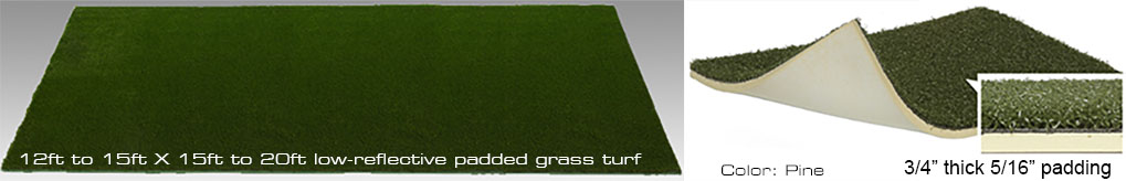
Example of low reflective turf:
6ft * 12ft less reflective padded turf grass mat suitable for camera systems
Price $399 + $99 shipping
You may find that the turf carpeting you are already using works well too so try this first
![]()
Q 14
Q 14 : How can I increase the range left and right of the SX line scan camera ?
A: Once again - If not using the latest SX camera - you'd require the SX op-amp upgrade and the new lens (cost for the upgrade with lens is $149 plus shipping)
In addition - as the increased 70 degree wide angle lens is only really of use if lighting is also available at these angles -
two extra IR LED lamps (cost around $70 each) mounted left and right of the SX camera would be required
Note that you can also use multiple SX cameras to increase the ball detection range but this method is a lot more expensive
![]()
Q 15
Q 15 : How can I adjust the carry distances when they are not correct?
Ball speed - and thus carry - is calculated by the length of the ball trace in the Vcam.
The speed of the ball is dependent on the distance the ball traveled within the camera time frame (shutter speed).
The camera sees only pixels so a real distance-to-pixel scale factor must be used to calculate the real distance traveled.
Thus, adjusting the Scale factor will alter the measured ball speed which in turn will adjust the distance/carry the ball will have in the golf simulation software.
Before adjusting the scaling factor, check the below described possible issues and factory calibration settings
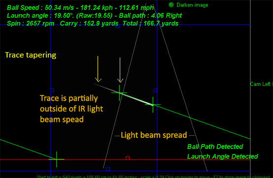
As measured ball speed is directly proportional to the length of the ball image trace , it's important that the ball trace from beginning to end is well illuminated.
With really fast high speed shots, it is possible that the ball won't be sufficiently illuminated to leave a solid trace and appears to taper out towards the end.
The image processing software in this case won't detect the full length of the trace and thus the measured ball speed will be too slow.
In order to avoid this problem you either need to tilt the IR Lamp further towards the screen
or additional illumination (either IR LED or Halogen) has to be added further ahead towards the screen.
In addition, an IR LED lamp should be mounted next to the Vam so that the ball is also illuminated from the side.
The side mounted Vcam IR lamp should be tilted upwards around 18 degrees
Camera calibration
All current GSA Golf Control Panel versions and updates now include a factory set camera calibration table
that negates any user requirement to calibrate the cameras themselves.
The table consists of 3 calibration tables each consisting of 126 entries
for various distances the Vcam is from the left line
Vcam distances from the left line are 5ft, 6ft and 7ft.
Note that the calibration table "calibLRex.csv" is placed in the "C:\Program Files (x86)\GSAControlPanel\data" folder when you download the latest CP update.
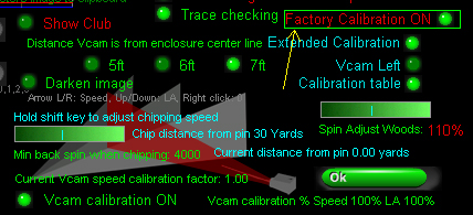
In order to use it, the new "Factory Calibration" option must be on.
Calibration factors used now displayed
The calibration factors used for the current shot are now displayed in the Vcam window.
These are Speed adjustment, Launch Angle (LA) adjustment and the index number into the calibration table.
In the above example, the raw speed of the ball was reduced to 84% and the raw LA increased by 38%
Extended calibration "Scale" factor = 0.2780
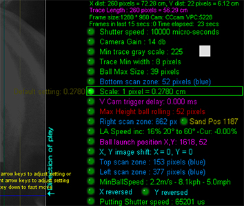
Note that the Scale factor for the calibration tables was set to 1 pixel = 0.2780.
This scale factor used with the calibration tables should result in exact ball speed measurements across the entire 0 - 60 degree launch angle and +/- 20 degree path range.
Increasing or decreasing this scale will result in decreased or increased measured ball speed across the entire range should you care to change it.
Don't forget !
If your Vcam is mounted on the left side of the enclosure, ensure that the "Vcam Left" option is ON
otherwise your calibration will be reversed
Also don't forget to set the distance your Vcam is from the enclosure left line
Currently distances are 5ft, 6ft and 7 ft.
If your Vcam is over 7 ft away from the left line then just use 7ft setting for now.
Other distances will be available later this year
Also don't forget to set the amount of calibration to 100% for both speed and LA to start with
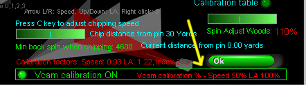
Later you can reduce or increase the amount of calibration for both Speed and LA to suit
In the above example the speed calibration was reduced to 50% so that any ball speed adjustments for ball hit left or right will be 50% less
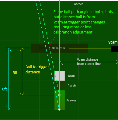
Note that the calibration tables where made with a ball to trigger distance of 5ft.
And don't forget to set "Extended Calibration" ON and "Factory calibration" ON
Note that these are default ON with the new CP releases
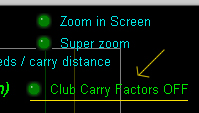
The carry factors ON/OFF button is at the top of the Vcam window
And finally, don't forget to switch "Carry factors" OFF
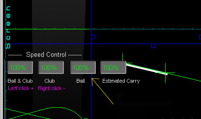
Select the "Adjust speeds/carry distances" ON at the top of the Vcam window
and "Ball speed controls" to their default of 100%
Click the above button to read how to calibrate the cameras yourself.
![]()
Q 16
Q 16a: Why, when I adjust the carry distances for woods and long iron shots to the correct carry distances
are my short iron shots then too far ?
Q 16b: Why, when I adjust the carry distances for short irons to the correct carry distances
are my woods and long iron shots then too short ?
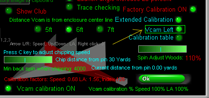
Actually this shouldn't occur with the calibration set on but in case it does, you can use the "LA Speed" adjust factor in the Vcam window
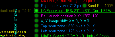
The LA Speed adjust factor will adjust the measured speed depending on its launch angle
In the above image example, a maximum speed increase of 16% will be applied at a launch angle of 60 degrees
This 16% speed increase will be spread over a launch angle range from 20 degrees to 60 degrees
i.e at 20 degrees or less there will be no increase in speed
at 40 degrees (i.e. half way between 20 and 60 degrees) an 8% speed increase will be applied
The "increase speed with increasing LA" method is used to fix carries that are too short for short irons but okay for long irons and woods.
Note that this speed adjustment can also be reversed so that the measured ball speed will decrease with increasing launch angles.
The "decrease speed with increasing LA" method is used to fix carries that are too long for short irons but okay for long irons and woods.
Use the left / right arrow keys to set the adjustment to minus (i.e. -16% or less)
The "LA Speed inc" text will then read "LA Speed dec"
"inc" stands for Increment and "dec" for decrement
Is the Club Carry Factors option set ON?
The carry factors ON/OFF button is at the top - right side of the Vcam window
If the option is set ON then check the carry factors table
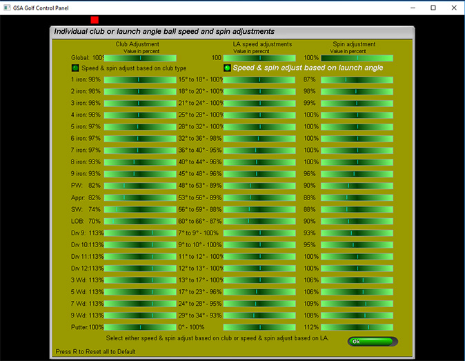
This table allows you to add speed / carry factors for each club or launch angle separately.
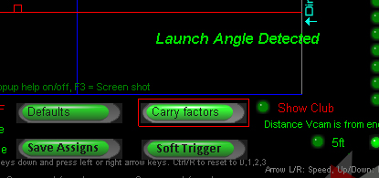
Click the "Carry factors" button to open the carry facotrs table.
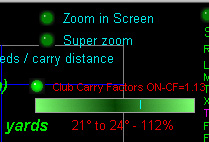
There's a new slider bar in the Vcam window that allows users to adjust the LA based carry factors directly in the Vcam window and thus see the results of carry adjustment immediately.
Note that the "Carry Factors" option has to be set ON in order for them to take effect
There's also a "Driver boost" factor in the Setup window that just adjusts ball speeds for Drivers
![]()
Q 16 C
My shots are inconsistent. My carry distances are all over the place.
Check the following:
1. Is the complete length of the ball trace in the Vcam being detected?
In order for the system to measure the correct ball speed, the complete length of the ball trace has to be detected in the Vcam.
The above image shows a ball trace length that is only partially detected and thus a far lower ball speed is being measured.
Fix: If you see that the trace appears to be fading out at the far end then add an additional IR LED light to additionall illuminated long traces.
2. Are "Carry Factors" switched on ?
Check the factors if this feature is on.
3. Is "Factory Calibration" switched on ?
If ON then check that the "Vcam left" is not ON in the Vcam window if the Vcam is mounted on the right side of the enclosure
and that it is ON if the Vcam is mounted on the left side of the enclosure.
Click the above button to read more about camera calibration
![]()
Q 17
Q 17: How can I adjust the chip and putting distances when they are not correct?
Go to the putting and chipping page to see how to do this
![]()
Q 18
Q 18 : Why do balls hit left go further than balls hit right (or vice versa)?
If your Vcam is mounted on the left side of the enclosure, ensure that the "Vcam Left" option is ON
If your Vcam is mounted on the right, ensure that the "Vcam Left" option is OFF
otherwise your calibration will be reversed
Also don't forget to set the distance your Vcam is from the enclosure left line.
i.e.5ft, 6ft or 7ft
![]()
Q 19
Q 19 : I don't see "Factory Calibration" in my Vcam window
You must be using an older version of the Control Panel.
Go to the "Tech News" page and download and install the new version of the GSA Golf Control Panel
![]()
Q 20
Q 20 : Shots are always going left or straight (or right and straight)
Check your ball launch positions in both regular shot mode and putting mode in the Hcam window


![]()
Q 21
Q 21: How can I prevent inadvertent ball launches when I go to retrieve balls lying around in the enclosure area
As of CP version 8.8.2.5 you can use the software method
New "Software Swing Detector" prevents inadvertent ball launches in game when retrieving balls
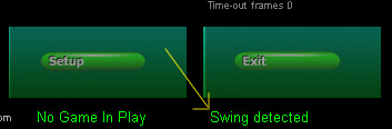
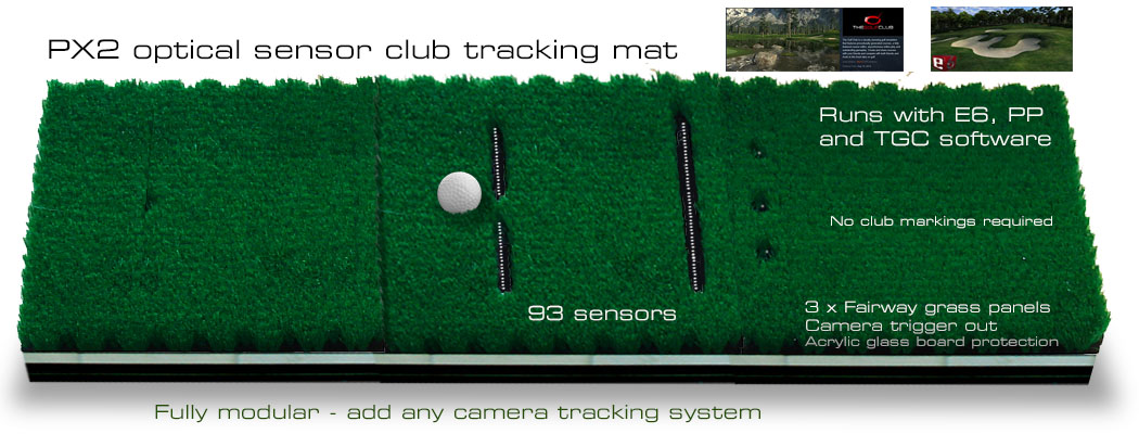
If you have a CTS club track camera with trigger mat or a PX2 club track sensor mat (as with the PX5) then you can optionally setup the system so that it will only launch a ball if a swing (or any movement) over the mat is detected.
You should see a new "Swing detected" message at the bottom right hand side of the CP's main window after a swing. This message appears for about 2 seconds.
Shots will only be detected by the V and H cams during this 2 second window so you can walk freely around the enclosure without any inadvertent ball launches.
Note that this option requires that all shots are made from the mat - including putting unless the "Allow putting without swing being detected on mat" is set on
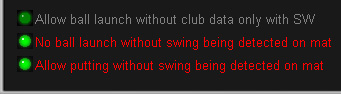
Switch the "No ball launch without swing being detected on mat" in the CP's Setup window.
Inadvertent shots when retrieving balls solution
as of this version:
1. set the option "No ball launch without swing being detected on mat" ( this is now for both camera club tracking mats as well as optical sensor -px2 - mats.
This simply means that if some kind of swing was detected on the club tracking mat ( it doesn't have to be valid, just that data or frames came in ) then - and only then - do we allow the shot to launch either with or without club data.
No launch when putting if the Vcam captures data
2. set the option "Allow putting without swing being detected"
When putting, the "No ball launch without swing being detected on mat" won't work because you won't be putting from the club tracking mat.
Solution:
A putt is only recognized if the Hcam sees the ball but the Vcam doesn't as the Vcam's valid FOV is set to higher level than a rolling ball.
Thus, if the system is in putting mode or a putter has been selected and Vcam data has been captured, we don't launch the ball.
i.e. if walking around the enclosure in order to retrieve balls you will certainly trigger both the H and V cams and in this case we dis-allow the launch.
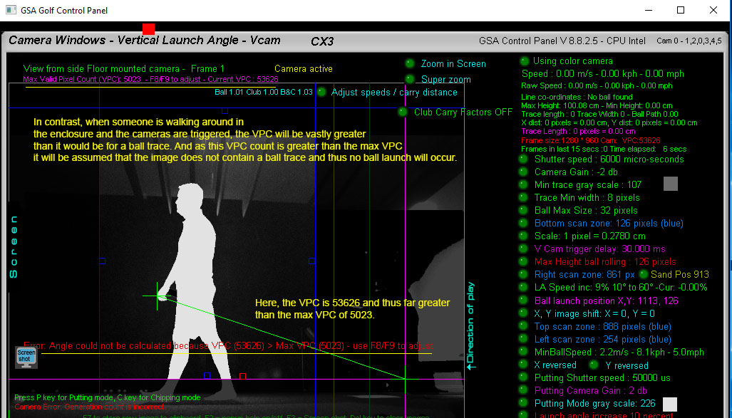
No launch when valid pixel count in the Vcam is over the user defined maximum
In addition to the above methods of preventing a launch when retrieving balls, the CP features a "Valid Pixel Count" known as VPC.
The VPC counts the number of valid pixels - i.e. the number pixels in the Vcam that are equal to or are above the "Min Gray Scale" setting.
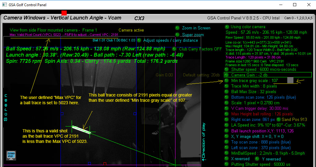
If the VPC count is less than the max VPC then it will be assumed that image contains a ball trace and the ball will launch
Note that this method won't work if the player just reaches out with his club to retrieve a ball as club head can look like a small ball trace.
In this case, either the player shouldn't use a club to retrieve balls or the club tracking swing detection method should be used.
Setting the max VPC value
To set the max VPC value, simply strike a number of balls and note the current VPC count displayed in the Vcam window after each shot.
You'll probably find that - even with the longest shot - this value will be in the 2000 to 9000 value.
In this case, set the max VPC count (using the F8 - to decrease and F9 keys - to increase) to the max value you've seen plus a tolerance of 500 of so.
Alternatively, use one of the below add-on products
New "Line Scan Shot Detector" prevents inadvertent ball launches in game when retrieving balls
Occasionally inadvertent ball launches may occur when walking within the line scan area - usually to pick-up balls.
The addition of this new line scan camera placed halfway between the Hcam and hitting area will prevent this.
The "Line Scan Shot Detector" is used as a trigger gate that only allows the main line scan camera's trigger signal to pass through to the ball V and H cameras if an object passes through its FOV.
It can also be used to detect if someone is standing at or close to the hitting position and thus blocks the main trigger signal if no one is at the hitting mat.
Price: $ 499.00
New "Optical Sensor Shot Detector" prevents inadvertent ball launches in game when retrieving balls
A lower cost alternative to the line scan camera shot detection, is to use an optical sensor shot detector. This sensor is emedded in the hitting mat just in front of the ball launch position.
Up to 3 sensors can be used: one in the hitting mat for regular shots, one on green surface for putting and one for the rough or sand shots.
Price: $ 199.00
![]()
Q 23
Q 23 : I don't have a disc drive on my PC. Can I download all the installation files?
Yes.
Contact us for all software download links
![]()
Q 24
Q 24 : Why are my ball traces appearing so faint ?
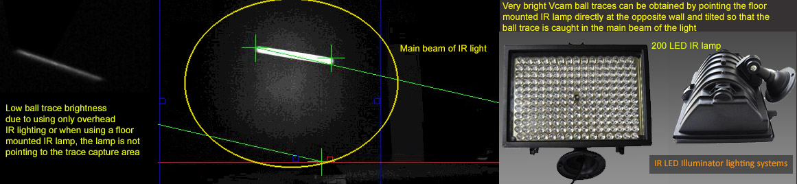
The Vcam ball trace brightness can be substantially increased by using high intensity narrow beam IR lamps next to the Vcam that are pointed at the trace capture area.
The above 200 LED IR lamp costs just $64 on Amazon
![]()
Q 25
Q 25 : My H cam camera is detected but doesn't capture new images even in video stream mode
This is usually due to the long USB cable length required for the Hcam
To fix: use powered USB hubs for every 10ft of USB cable and power the cameras with external 5v power supplies.
Note: separate USB power connectors on our cameras are a relatively new addition so
if your Hcam camera doesn't feature a separate USB power connector (i.e. it's an older camera) then you can send it in to us to have one fitted
![]()
Q 26
Q 26 : How do I take screen shots
Take a screen shot and automatically save it to a jpeg file
Note that we often require customers to make screen shots of their camera windows in the Control Panel during the support period
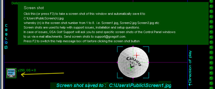
There's a "Screen Shot" button on the left side of all the main screens in the Control Panel.
This function takes a clear screen shot of the current window and automatically saves it to a jpeg file that can be sent to us via an e-mail attachment for us to analyze.
A main reason for making this feature is that many customers are still sending blurred screen shots from photos made with their iPhones to us that are difficult to read.
We put videos on the web site on how to make screen shots but still many find it easier to just take a photo. So now there's no excusues.
Note the screen shot number shown in the message after taking a screen shot.
All screen shots are saved to the "C:/Users/public" folder
![]()
Q 27
Q 27 : How to avoid Lens ghosting
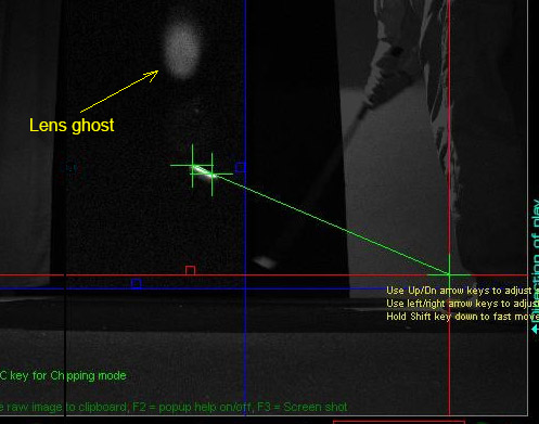
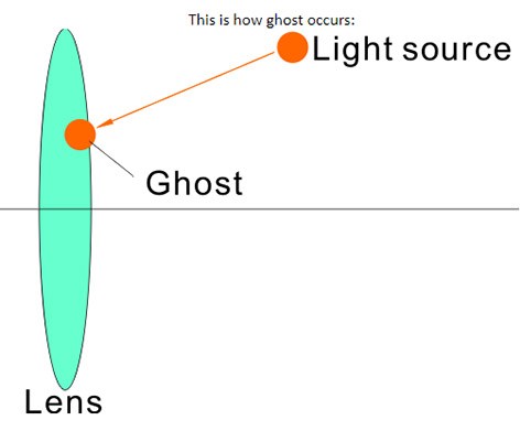
Are you seeing light spots in the Vcam images on the back drop that aren't actually there on the back drop?
The phenomena is known as "Lens Ghosting" and is caused by light from the ceiling mount IR lamp hitting the IR filter at an angle greater than the lens angle.
i.e. the IR light is outside the FOV of the camera so you don't see the light itself but its reflection is still there.
Lens ghosting like this can cause havoc with the CP's image processing as it may well be picked up as part of the ball trace.
There are three ways to eliminate this issue:
1. Place a hood on top of the Vcam camera case that extends some 4 to 5 inches out.
We are now supplying hood cover flaps with new systems so contact us if you didn't receive them.
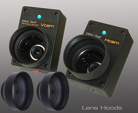
In the meantime cut a piece of card 4" x 6" and tape it to the top of the Vcam.
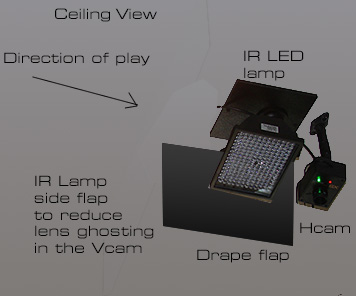
You can also attach a flap to the side of the Hcam to prevent light from the floor mounted camera.
Attach it to the same side as the floor lamp so that it extends down 4 to 6 inches.
2. Tilt the Vcam camera further down.
In so doing, if the FOV of the camera is not wide enough to pick up high lofted shots then the camera has to be mounted further away from the left line of the enclosure
If - due to space restrictions - it is not posible to move the Vcam further away from the left line of the enclosure
then use the new "Hcam launch" feature as described below.
3. Use a side flap next to the IR LED lamp.
Hcam launch for high lofted shots that are out of the FOV of the Vcam

As it's possible that the ball trace with very high lofted shots will be out of the FOV of the Vcam camera, we've added a new feature that will allow the ball to launch with just the H cam data.
Switch this feature on or off in the Hcam window (lower right side of screen).
Note that this feature has 3 modes. 1. OFF, 2. only ON when in chipping mode, 3. Always ON
Default is 3. Always ON
When ON and a valid shot is detected in the Hcam but no valid trace is detected in the Vcam, the speed and direction of the of the ball will be measured just from the Hcam.
Vertical launch angle will be taken from the loft of the selected club.
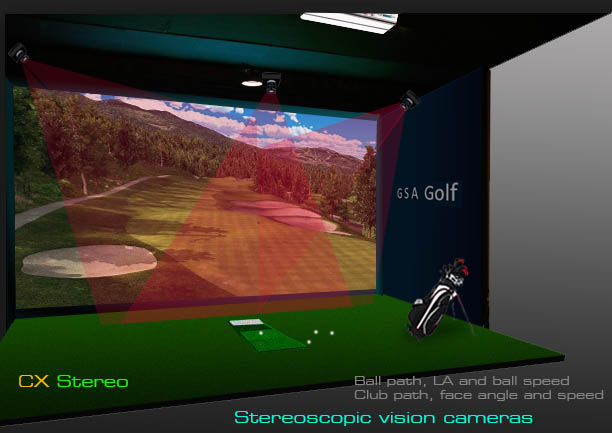
4. Use the new stereoscopic vision system
The new stereoscopic software - which will soon be available - requires that both H and V cam cameras are ceiling mounted and point straight down.
This configuration eliminates any danger of lens ghosting as all lighting will also be ceiling mounted and thus both cameras are pointing away from the lighting.
![]()
Q 28
Q 28 : There is a lag time between me striking the ball and it launching in the game software. How can I fix this?
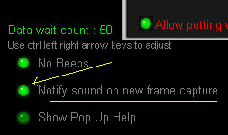
Data wait count
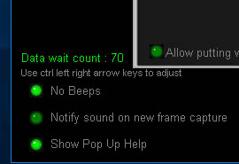 The data wait time value is visible in the Setup window of the CP as of version 8.8.1.8
This number is used to force the CP to wait until club or ball spin data has been sent to the CP
Usually the V and H cams will capture the ball before club data coming over slower lines arrives at the CP.
In order to prevent the ball from immediately launching without club data in the game
the system will wait a while for the club and or spin data to arrive.
The wait counter is set to this value when both the V and H cams detect a shot.
If this number counts down to 0 then the shot will be launched with just the ball data from the V and H cams.
If you notice a significant delay between striking the ball and the ball launching in the game, reduce this wait count value in the Setup window of the CP to around 10.
Note that this feature is only available as of V.8.8.1.8 of the CP
![]()
Q 29
Q 29 : With fast shots that have long ball traces, the trace extends into the screen area and thus the correct ball speed can't be measured.
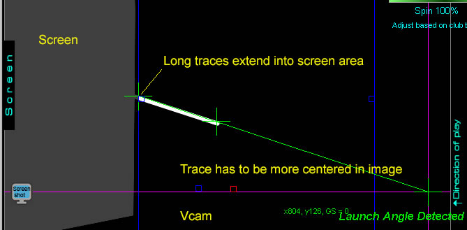
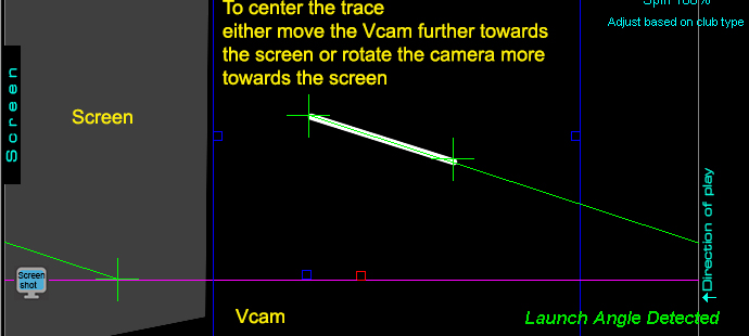
In order to measure the correct ball speed, the full length of the trace must be detected in the Vcam.
The trace should therefore be centered in the valid FOV of the camera. To do this, simply move the Vcam further towards the screen of rotate it further towards the screen.
CTS Club tracking Q & A
Q CTS 1:
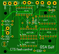
The CTS flash is being picked by the SX line scan camera and preventing the V and H cams from detecting a ball launch.
How to I fix this?
A: Most probably the CTS unit is too near the SX camera
Minimum distance the CTS should be from the line scan camera is 7 to 6ft
If less than this then the flash will probably prematurely activate the SX cameras which - in turn - trigger the V and H cams and thus miss the ball.
To fix:
Either move the CTS and the hitting mat position further back from the SX camera
or
replace the SX camera with a trigger array
Trigger arrays are not effected by any CTS flashes
![]()
Drape flaps
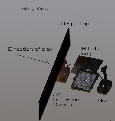
A drape flap (a piece of heavy black drape 3ft or so wide and 1 ft or so long) mounted just behind the cameras on the ceiling can be used to shield the cameras
from high flying balls and helps prevent ambient light or CTS flashes from getting into the SX line scan camera.
A drape flap mounted in front of the CTS unit will also help to block the flash light from being picked by the SX line scan camera.
PX Installation Q & A
![]()
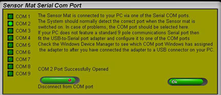
Q PX-1:
The PX2 sensor mat is connected to the PC but the Control Panel states
"No COM Port IO" and "Sensor mat not detected"
A: "No COM port IO" means that the Control Panel couldn't open the COM Port
Check that the COM setting in the Control Panel "Sensor Mat Com Port" window corresponds to the COM port in the Windows Device Manager
Click the above image to read more about the PX COM Port Settings
![]()
Q PX-2 :
The PX2 sensor mat is connected to the PC but when I click on the "Connect to COM Port" button the Control Panel states
"Access denied"
A: Switch the "Serial Enumerator" setting OFF in the Windows Device Manager COM Port Advanced settings
Click the above image to read more about the the "Serial Enumerator"
Q PX-3 :
The PX2 sensor mat is connected to the PC and the Control Panel states
"Sensor mat detected"
but the screen keeps flashing "Reset ON, No light over sensor mat"
A: Light is not getting down to one or all of the 3 reset sensor at the back of the mat.
Ensure that the overhead halogen lamp is pointing directly down and over the mat.
Ensure that light is actually getting down on to the 3 reset sensors and nothing in the 3 holes is obstructing the light.
Either move the light back or the mat forward so that the overhead halogen light is directly over the 3 reset sensors at the back of the mat.
![]()
Q PX-4 :
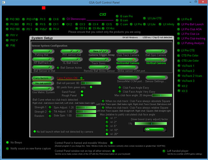
Why does my PX2 club tracking mat sometimes read exaggerated club face angles
A: Usually this only occurs if the ball is not being played from the tee holder position on the sensor mat.
When playing the ball from behind the tee holder, the ball will trigger the club face angle sensors instead of the club and thus erratic club face angles will be detected.
Important: always play the ball from the tee holder with the PX2 sensor mat. i.e. either with or without a tee
Other reasons are: woods and drivers have rounded faces and thus the club face angle cannot always accurately detected .
Unfortunately this is an inherent problem with all optical sensor club tracking mats, no matter from what manufacturer.
Another possible cause can be the lie angle of the club at impact being too steep and thus letting light get under the club so that the sensors are being triggered unequally.
Other than replacing the sensor mat with a camera based club tracking system, there's no absolute fix for the problem.

However, these last two causes can be greatly lessened by setting the max measured club face angle to a lower value - like 11 degrees as in the above image.
or selecting one of the "Club face easy" options in the CP's Setup window.
![]()
GSA Golf Game software download

Warning! if you already have the full version GSA Golf /RedChain software installed, downloading this free single course version will prevent the full version from running correctly
Putting and Chipping
Q PUTT-1
When putting, the ball flies over the green for 50 yards and more.
This is most likely due to the Vcam picking up illuminated bright flooring
See the putting page for details on how to setup putting
Q Chipping-1
When chiping, the ball only carries a few yards
This is most likely due to the "Chip ball speed adjust" setting being too low.
Check to see that the "Chip ball speed adjust" is not lower than 50%
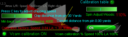
Chipping Ball Speed adjust
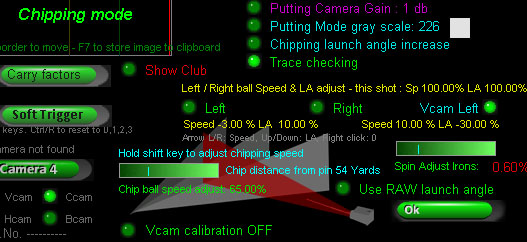
We've introduced a new "Chipping Mode" feature that allows you to set a ball speed adjust factor, minimum spin rate and a launch angle adjust factor when chipping.
Chipping mode automatically kicks in when the ball is within the User Defined chipping mode distance from the pin but not on the green.
For tests purposes you can manually set to "Chipping Mode" by pressing the "C" key on your keyboard.
Note that switching the "Chipping Mode" on or off with the "C" key is only possible if a game is not in play.
Holding the keyboard "Shift key" down converts the "Min ball spin rate" slider bar into a chipping ball speed adjust factor.
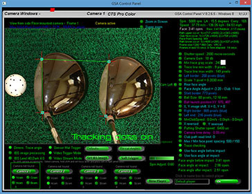
The above screen shot shows that the measured ball speed of the chip has been reduced by 65% and that the chip distance has been set to 54 yards.


![]()
-
-
-
-
 Home
Home Sensors
 Cameras
 Software
 Enclosures
 GSA Courses
 E6 Courses
 Business
 Tech News