![]()


![]()

![]()
![]()
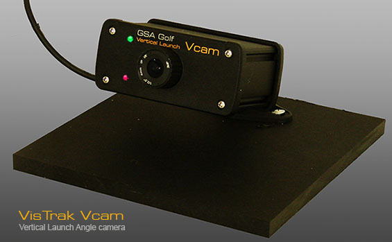
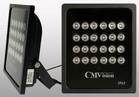
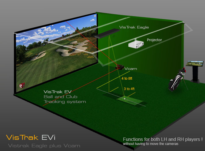
Floor mounted Vertical launch angle camera
add-on to VisTrak Eagle
Functions for both Leff and Right handed players without having to move the unit.
Camera includes CM Vision IR LED lighting
$ 1,499.00

![]()

VisTrak Eagle + Vcam
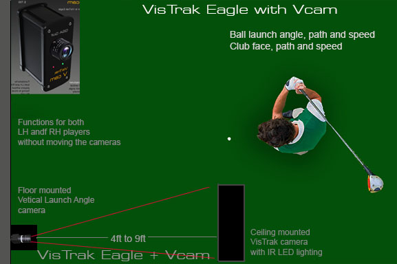
VisTrak Eagle with Vcam Vertical launch angle detection
withVisTrak Eagle lighting
Price includes 15ft USB 3 cable and 15ft USB3 extension cable for a total length of 30ft
GSA Golf 18 hole course game software with driving range included
plus 1 year E6 Connect 18 hole course included
$ 3,499.00
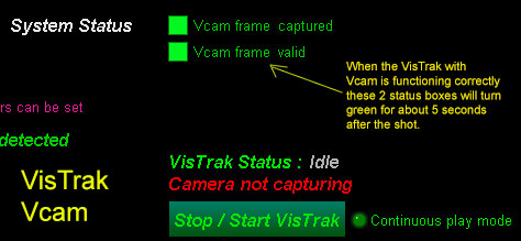
VisTrak Vcam Setup
Please note:
If you are new to GSA Golf systems, it is recommended to first setup your VisTrak EV system in two stages:
1. Just as a VisTrak Eagle so that basic play is possible
2. after you have the VisTrak Eagle up and running and you are able to play a round or 2 of simulated golf in VisTrak Eagle mode,
then add the Vcam camera to the system

VisTrak Eagle Setup
Click on the above link to see how to setup the VisTrak Eagle camera.
![]()
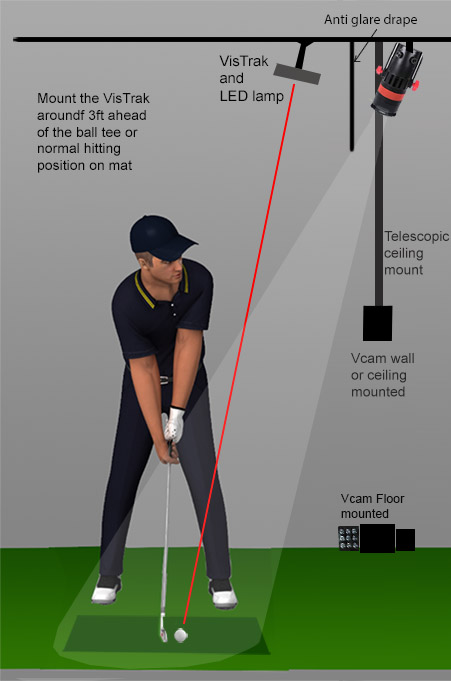
The VisTrak Vcam's main purpose is to detect the vertical launch angle of the ball when used with the VisTrak Eagle.
In our CX2 systems the Vcam is also used to measure ball speed by measuring the length of the ball trace
but when used with the VisTrak Eagle, it's main use is to measure vertical launch angle.
Note that the super bright green LED on the Vcam is the same "looking for ball" and "ball detected" indicator as on the ceiling mounted VisTrak Eagle.
As the Vcam cam is floor mounted, this indicator will be more visible to the player.
 --
--
1. Place the VisTrak Vcam camera and IR LED lights around 3 ft or 4 feet ahead of the ball strike zone
on either the left or right hand side of the enclosure.
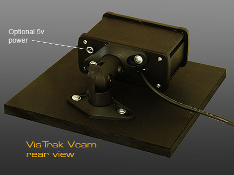
2. Connect the Vcam camera USB 2 cable to a port on the PC
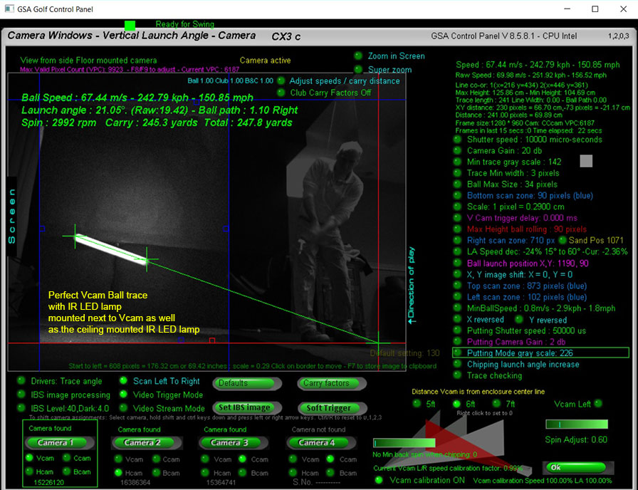
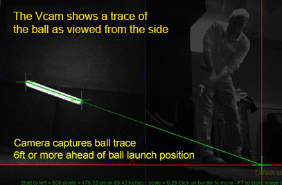
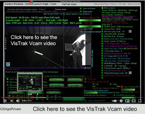
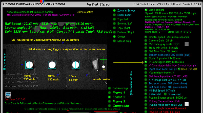
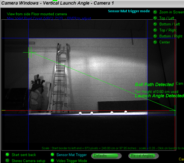
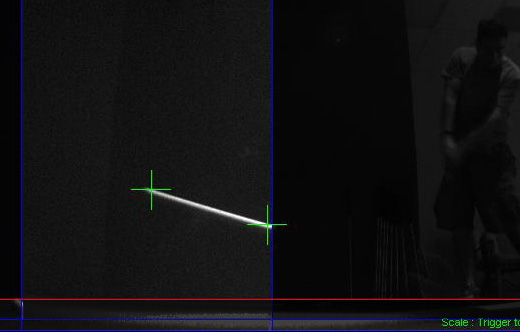
The Vcam vertical launch angle camera views the ball from the side and - due to its long exposure time -
the image of the ball is a white trace.
The camera field of view is actually far greater than what is actually required
and captures the player (on the right), the projection screen (on the left) and the floor.
The blue border lines dictate the valid field of view - i.e. the area where the system will be looking for the ball -
and the red line dictates the maximum ball height a ball will have to be considered as a rolling ball or sculled shot.
Note that the length of the ball trace is directly proportional to the ball's speed
and providing the camera's exposure time (10 milli seconds here) and the pixel to cm scale (0.2 here) is constant - which it always is - this correlation is constant and consistent.
i.e. no matter what the launch angle is, the length of the ball trace will always be the same for a given ball speed and will always be directly proportional to the ball's speed .
Note the strong contrast between the background and the ball trace.
This is achieved by setting the camera gain high which amplifies the contrast.
The ball is illuminated by the overhead and / or side mounted IR LED lamps.
LA Image feature in the VisTrak window
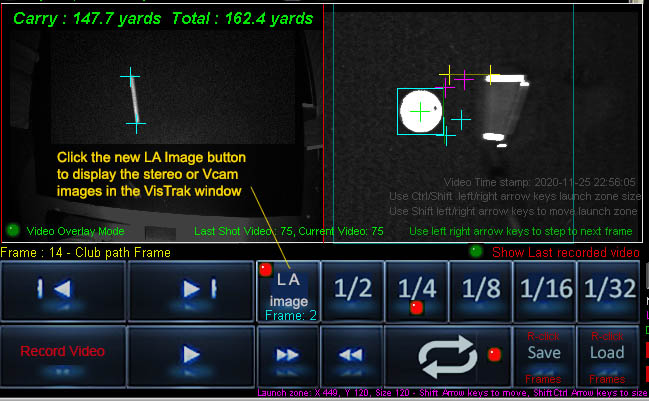
When using VisTrak Stereo or VisTrak Vcam systems, it's often useful to be able to view the stereo or Vcam Launch Angle images
directly in the Video without having to switch over to the CP and go into the CP camera windows.
Click multiple times to step through the fames if using a stereo system with 2 or more frames.
This feature is also in the Video Overlay window .
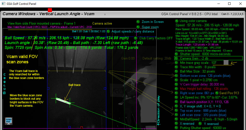
VisTrak Vcam - most important settings
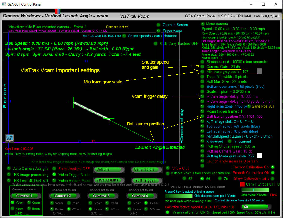
The above image shows the most crucial and important Vcam settings.
1. Shutter speed and gain
Set to around 10,000 us - long exposure so that the ball is seen as a ball trace i.e. motion blur
and 20 db - i.e. high gain.
2. Min trace gray scale
Set so that the ball trace is detected. i.e. the ball trace brightness (the gray scale level) has to be higher than anything else in the image.
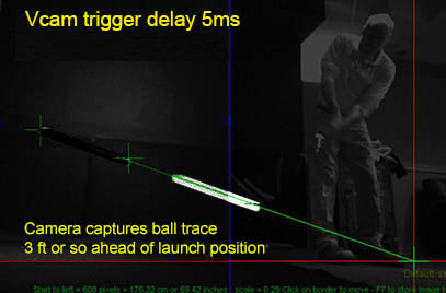
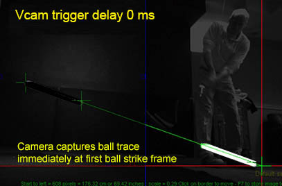
3. Vcam trigger delay
Set to around 5 to 10 ms so that the ball has time to leave the launch position and its trace is in the FOV of the camera
4. Ball launch position
Manually set this to where the ball is to be played from in the image
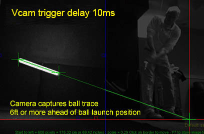
Vcam trigger frame and trigger delays
The Vcam camera is triggered to capture 2 freeze frames from the VisTrak Eagle camera.
It is important to set the timing of this trigger signal so that the Vcam ball images are within the FOV of the Vcam cameras.
If the trigger signal is fired too soon then the ball images will be captured before the FOV of the camera and if fired too late
the ball images will be beyond the FOV of the Vcam camera.
Trigger delay options for VisTrak Stereo or Vcam systems
There are three methods of setting the camera trigger delays:
1. a camera fixed trigger delay setting for all shots and clubs
2. a club depedent trigger delay that changes the delay when a new club is selected or used
3. a variable ball speed dependant trigger delay
1. Vcam camera fixed trigger delay
In the Vcam camera window of the CP, set the trigger delay
You may have to experiment a bit to find the ideal trigger delay so that the ball in-flight is in the FOV of the cameras for all shot speeds.
A trigger delay of around 10 ms should be good though.
2. Club depedant trigger delays
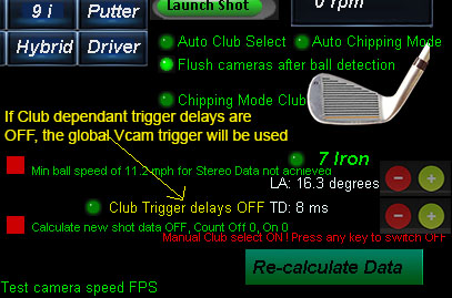
You can switch the club dependent Vcam or Stereo camera trigger delays on or off from the CP's main window.
Note: this feature is as of CP version 9.5.2.2 Beta
If off, then the regular Vcam trigger delay - as displayed in the Vcam window - will be used.
3. Variable Ball speed Dependant trigger delays
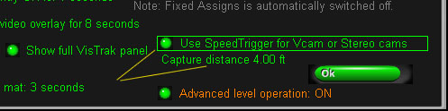
Switch on the SpeedTrigger for Variable Trigger delays from the Setup window.
Adjust the "Capture Distance" with the up/down arrow keys when the mouse is over the "Use SpeedTrigger" button.
The capture distance is where the Vcam or Stereo cameras will be triggered from the ball strike position so that the captured ball images
- no matter what speed they are traveling - will always be close to this distance.
This 3rd method is now the recommended way of setting the trigger delays
Note: This feature is only available as of CP version 9.6.5.1 or higher
![]()
Minimum ball speed for VisTrak Vcam.
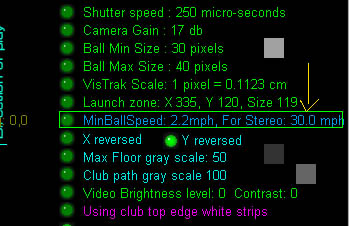
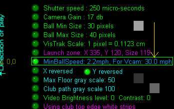
If the measured ball speed from the VisTrak Eagle is less than this user defined minimum speed,
then data from the Vcam camera will be ignored
and all launch data will be derived from the VisTrak Eagle.
This is done because data from the Vcam camera with small chips cannot be guaranteed to be correct
due to either the ball being too close to the club or the ball trajectory is already on the downwards path by the time the cameras capture the ball images
and thus the measured vertical launch angle will not be correct.
Use the left/right arrows keys to adjust the min speed for Vcam when selected.
Use the up/down arrow keys for overall min ball speed.
![]()
The two main windows are the VisTrak Video window and the Vcam Camera window.
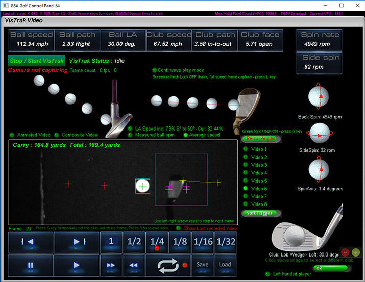
The VisTrak window is used to view the swing playback.
The camera windows are used to adjust camera settings like gain and shutter speed
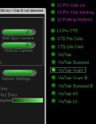
When VisTrak Vcam is selected, camera 1 in the Cameras window becomes the Vcam and camera 2 the VisTrak camera.
Camera Assignments
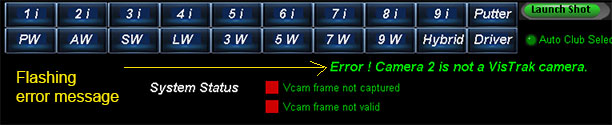
If you see this error message flashing when first starting the CP,
then the camera assignments are incorrect.
It is essential that the correct camera assignments are made.
An error message is displayed if any of the cameras are incorrectly assigned.
Correct camera assignments for the VisTrak Vcam are:
Cam 1 is the Vcam and Cam 2 is the VisTrak camera.
To check for correct camera assignments for the VisTrak Vcam ,
go to the cameras window in the CP and successfully click on the cameras 1 and 2.
If one of the these cameras is incorrectly assigned, a large error message will be shown.
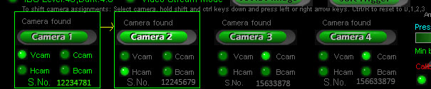
If you find that cameras are not being assigned in the correct order then you can manually re-assign the cameras.
To do this, select the camera in the CP cameras window, hold both the shift and ctrl keys down,
and press the left or right arrow keys to move the camera up or down the sequence.
Auto camera assignments
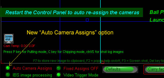
This new feature eliminates the need to manually assign the cameras
Simply switch on the Auto Camera Assigns option and restart the CP.
Using the Vcam to measure ball speed
The main function of the Vcam when used with the VisTrak camera is to measure vertical launch angle (LA).
However, it is also able to measure ball speed - select the "Measure ball speed from Vcam" option for this.
In order to measure ball speed, the complete ball trace has to be detected which may not always be possible as the Vcam is triggered from the VisTrak camera
using a Vcam trigger delay (which may not allow the complete ball trace length to be inn the FOV of the camera)
and not from a Line Scan camera (which always allows the complete ball trace length to be inn the FOV of the camera).
Note that when the Vcam is used purely for LA detection, the LA is measured from the user defined ball launch position and only one of the ball trace cross hairs.
So ball trace length, which requires detecting both ends of the ball trace - as in the above image - is irrelevant.
When used to measure ball speed however, the exact trace length has to be detected as the ball trace length is directly proportional to ball speed.
Due to lens perspective distortion, the initial measured LA from the Vcam image will appear slightly lower if the ball path
is away from the camera and vice-versa, higher if towards the camera.
The new Vcam calibration table in this CP update corrects this deviation.
![]()
Vcam image background
The Vcam is mounted either on the right or left side of the simulator room.
As such, it is pointing at the opposite wall.
This opposite wall should be dark and not have any bright objects on it
The above Vcam image is from a customer that obviously missed the instruction that the background in the FOV of the camera should be dark
This is what the background and a ball trace from the Vcam camera should look like.
Valid FOV blue scan zone borders
Use the blue scan zone borders to block out any bright objects or surfaces in the FOV of the Vcam camera.
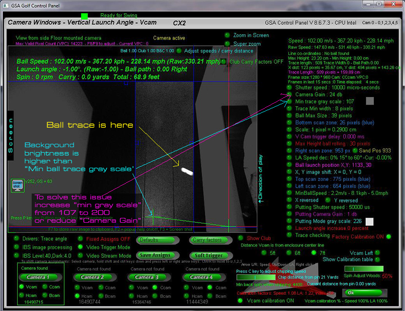
This opposite wall should always be darker than ball trace.

There are a number of important settings to be made in the Vcam camera window.
Click the above to read more about this.
VisTrak installation

Click the above to read about basic VisTrak camera installation.
![]()
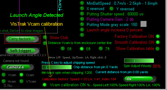
Vcam calibration
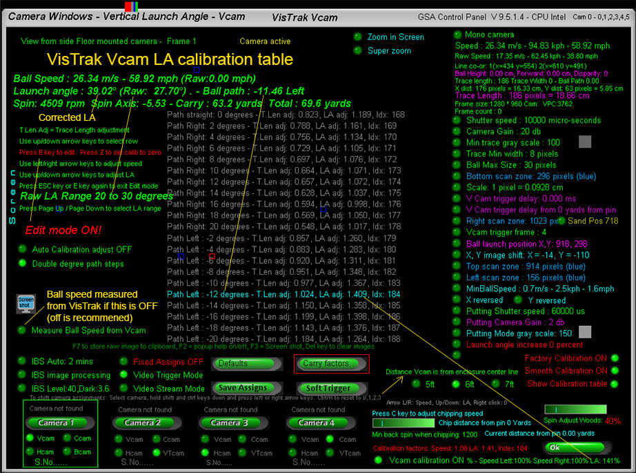
The VisTrak Vcam calibration table adjusts the measure ball LA depending on the ball path to correct lens perspective LA distortion.
In the above example, the ball path was 11.46 left and the Raw (unadjusted) LA was 27.7 degrees.
The LA adjustment table entry for this ball path and Raw LA is 1.409 (i.e. 140.9%) which then adjusted the Raw LA from 27.7 to 39.02 degrees.
The table is pre-populated with default values for 3 distances the Vcam is mounted from the enclosure center line (5ft, 6ft and 7ft)
so there shouldn't be any requirement to edit the table entries but you can if you wish. (press the "E" key to go into edit mode).
The table consists of 20 ball path entries for 10 degrees of Raw LA. i.e.
-20 to +20 ball path for Raw LA from 0 to 10 degrees
-20 to +20 ball path for Raw LA from 10 to 20 degrees
-20 to +20 ball path for Raw LA from 20 to 30 degrees
-20 to +20 ball path for Raw LA from 30 to 40 degrees
-20 to +20 ball path for Raw LA from 40 to 50 degrees
-20 to +20 ball path for Raw LA from 50 to 60 degrees
Use the keyboard Page Up and Page Dn keys to select the viewable range.
Using the Vcam to measure ball speed
The main function of the Vcam when used with the VisTrak camera is to measure vertical launch angle (LA).
However, it is also able to measure ball speed - select the "Measure ball speed from Vcam" option for this.
In order to measure ball speed, the complete ball trace has to be detected which may not always be possible as the Vcam is triggered from the VisTrak camera
using a Vcam trigger delay (which may not allow the complete ball trace length to be inn the FOV of the camera)
and not from a Line Scan camera (which always allows the complete ball trace length to be inn the FOV of the camera).
Note that when the Vcam is used purely for LA detection, the LA is measured from the user defined ball launch position and only one of the ball trace cross hairs.
So ball trace length, which requires detecting both ends of the ball trace - as in the above image - is irrelevant.
When used to measure ball speed however, the exact trace length has to be detected as the ball trace length is directly proportional to ball speed.
Due to lens perspective distortion, the initial measured LA from the Vcam image will appear slightly lower if the ball path
is away from the camera and vice-versa, higher if towards the camera.
The new Vcam calibration table in this CP update corrects this deviation.
User issue feedback
This one is from Mark, who is wondering why his VisTrak Vcam ball trace isn't being detected
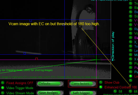
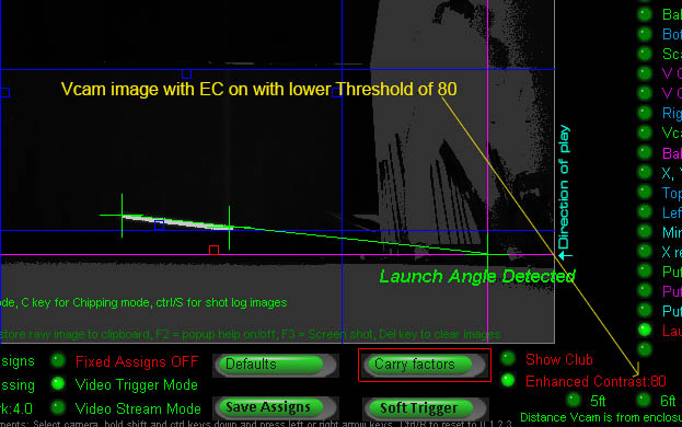
Mark seems to have switched Enhanced Contrast ON, but - because the threshold is set too high - the ball trace was darkened instead of being high-lighted.
Adjusting the Threshold down to 80 fixes the problem.
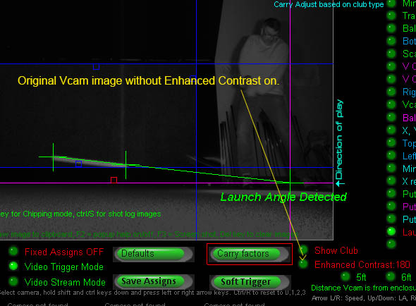
The original Vcam image from Mark was looking good anyway, so EC isn't really required in this case.
![]()
Technical Support


Email and remote access support is available for all original purchasers of GSA Golf systems.
For all non original purchasers (i.e. purchasers of used GSA Golf systems) remote access support can be purchased separately.
Click above images for more information.
![]()
![]()

![]()
 Home
Home Products
 Cameras
 Software
 Enclosures
 GSA Courses
 E6 Courses
 Business
 Tech News