![]()
![]()

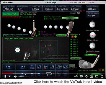
VisTrak Setup
![]()

Read this first
VisTrak Installation and Setup Videos
 -
-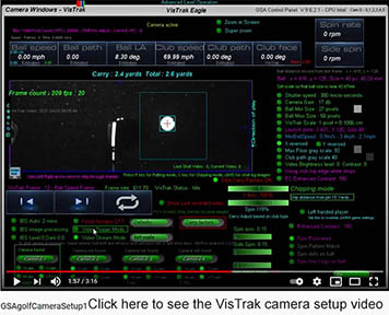
Click the above images to watch the VisTrak installation and setup videos
![]()


VisTrak problem solving.
This page will deal with common user VisTrak issues as and when they come in
![]()
Send us your shot video files
If you are experiencing issues with the VisTrak camera then the first thing to do is to send us (via email attachment) a copy of the video file of the shot for analysis.
All video files (.vid files) are stored in the C:\GSAgolf folder of your PC.
We will then get back to you with a solution to the issue.
![]()
GSA Golf system minimum PC requirements
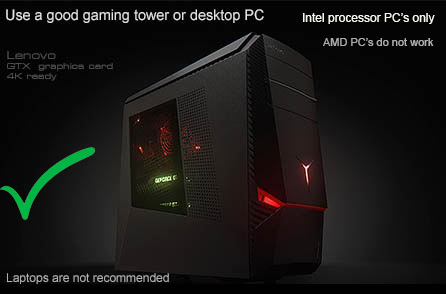
Intel i5 or above Processor
8GB RAM Nvidia 1070 Graphics Card or equivalent
(Dedicated GPU with DirectX 11 Support)
25GB of Hard Drive Space
Windows 10 (Required)
Internet Connection (Required)
When using VisTrak systems - Native USB3 ports (Required)
( i.e. no add-on PCie USB3 adapters for PCs that don't come with USB 3 ports as standard )
![]()
Cameras not registered?
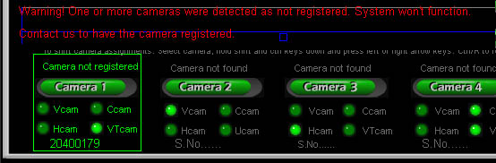
Cameras are registered in the Control Panel's executable program.
If you see the above message stating that the cameras are not registered,
then download and run the latest CP Beta or Alpha update.
![]()
Click the above button image to download the very latest Alpha CP update
Note: the above link is to the Control Panel updates only.
They require that the full version has previously been installed.
Without the full version installation, the CP application will not function.
![]()
VisTrak Installation Check List
1. VisTrak Camera and Light mounting
1. You have mounted the camera on the ceiling (no more than 10ft high) pointing at the ball strike zone?
2. You have either mounted a LED 65 watt plus visible light video spotlight with lens on the ceiling
or 4 high powered IR LED illuminators next to the camera pointing at the strike zone?
![]()
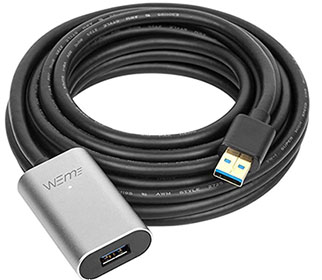
2. VisTrak Camera cables and USB 3 ports
1. You have confirmed that the VisTrak is connected to the PC with a USB 3.1 cable ?
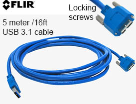
2. You have confirmed that the VisTrak is connected to a USB 3 port on the PC ?

The VisTrak camera is a USB 3 camera and must be connected to a USB 3 port on your PC.
You can identify a USB 3 port by the SS symbol next to the port
![]()
3. VisTrack camera operation
1. You have downloaded and installed all the software as described on the VisTrak Installation page ?
2. You have confirmed that the camera is running ?
![]()
Point Grey Cameras
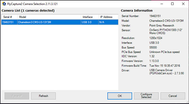
You can use the FLIR FlyCapture2 app to check that the VisTrak Point Grey camera is detected by the PC
The app is located in the
C:\Program Files (x86)\Point Grey Research\FlyCap2 Viewer\bin folder
and is called Point Grey FlyCap2
![]()
SSi Cameras
You can use the HuaTeng Vision application to check HT/SSi cameras
![]()
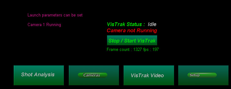
In the main window of the Control Panel you should see the "Camera 1 running" message
![]()
4. You have confirmed that the camera is operational ?
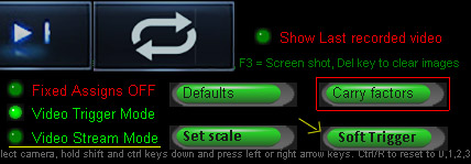
To confirm that the camera is operational, select the "Video Stream Mode"
or click the "Soft Trigger" button in the Camera window.
You should then see that new images are being grabbed and displayed
![]()
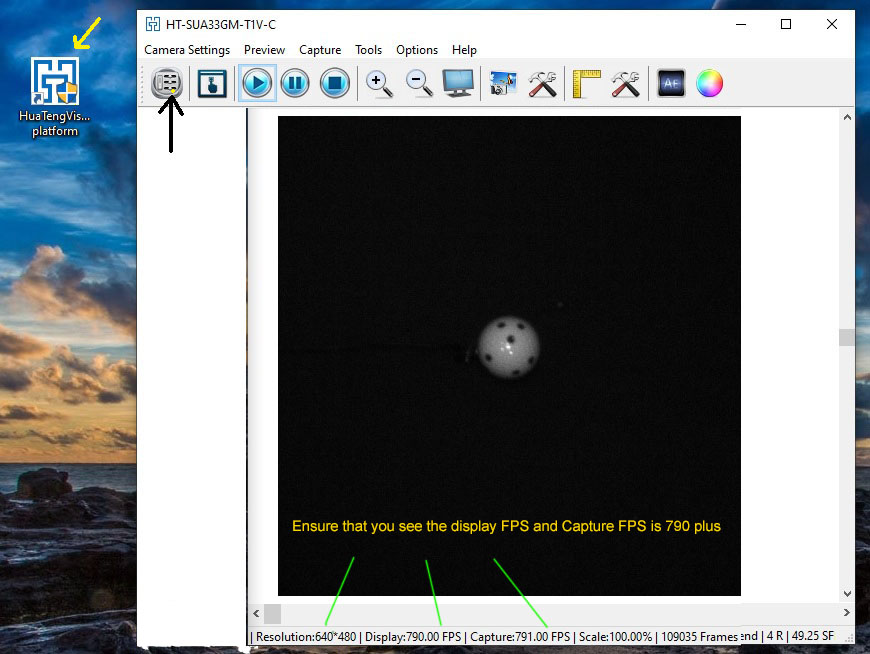
5. You have confirmed that the camera is operating at the correct speed ?
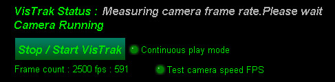
To confirm that the camera is running at full speed, click the " Test camera speed FPS" button.
After a few seconds, you should see that the fps rate is at least 590.
![]()
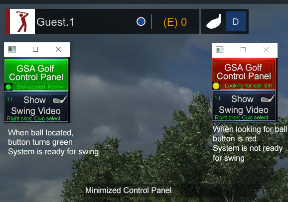
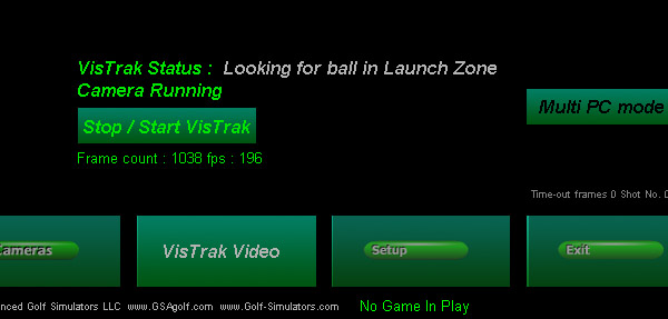
6. You have confirmed that the camera goes into "Looking for Ball In Launch Zone" after you have started the VisTrak camera?
![]()
7. You have confirmed that the camera detects the ball when placed in the launch zone
after you have started the VisTrak camera ?
To start the VisTrak camera, click the "Stop/Start VisTrak" button from the Control Panel's main window.
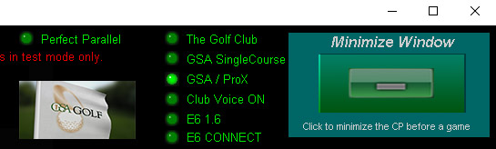
Note: when clicking the "Minimize Window" button, the camera is automatically started
If the ball is located, then you should see the above message in the CP's main window.
Important !
Once the ball has been detected in the launch zone,
do not waggle the club over the ball, do not bend over the ball and do not move the ball.
Doing any of the above will cause a shadow to be cast over the ball which will trigger the cameras
and may cause an inadvertent ball launch in the game software
and/or restart the "Looking for ball in Launch Zone" mode.
![]()
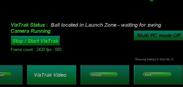
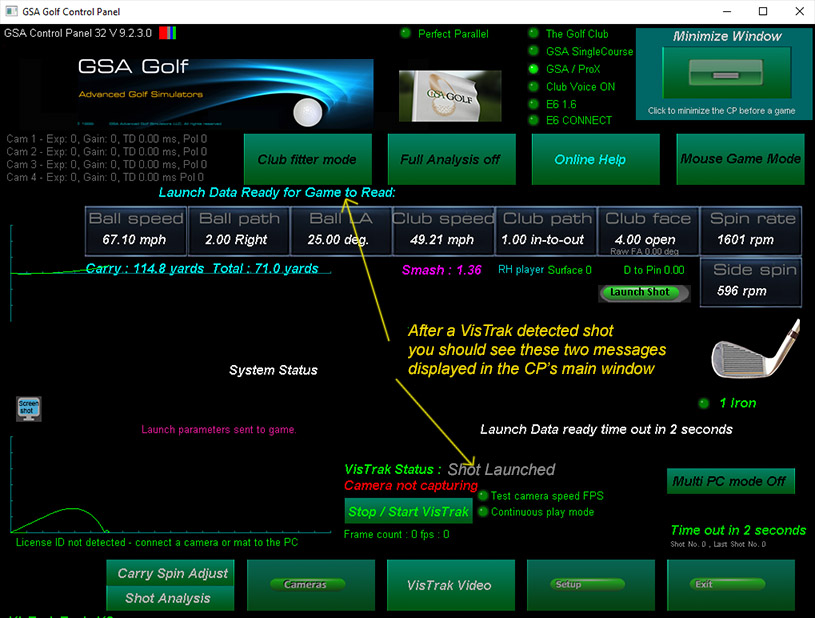
8. After striking the ball, you see the
"Shot Launched" and "Launch Data Ready for Game to Read"
messages in the Control Panel's main window ?
![]()
9. VisTrak video overlay setup
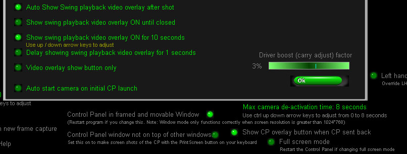
In order for the VisTrak video playback overlay to work,
the Setup settings should be as in the above image.
1. Control Panel in frames and movable window ON
2. Control Panel window not on top of other windows OFF
3. Show CP overlay button when CP sent back ON
4. Either the "Show swing playback video overlay ON until closed" or
Show swing playback video overlay ON n seconds should be ON.
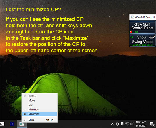
![]()
How to tips
How to move the CP game overlay button position
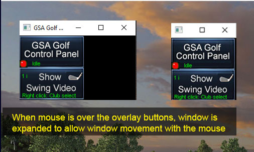
Alternatively, to move the buttons, hold the Ctrl Key down and click the CP Minimize button in the CP's main window.
While still holding the Ctrl Key down, use the up, down, left and right keyboard arrow keys to adjust the button positions on the screen.
![]()
VisTrak Problem solving
![]()
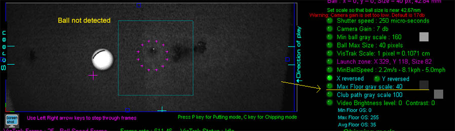
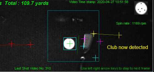
1. VisTrak not detecting shots
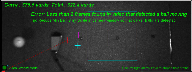
In order for the system to detect a launch, at least two frames must contain images of the ball in motion.
In the above frame image, the second frame of the video didn't detect the ball.
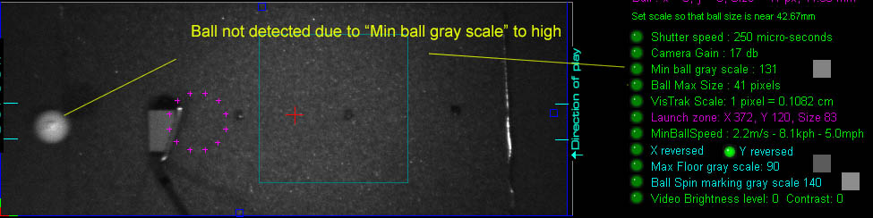
The reason for this was that the "Min ball gray scale" was set too high.
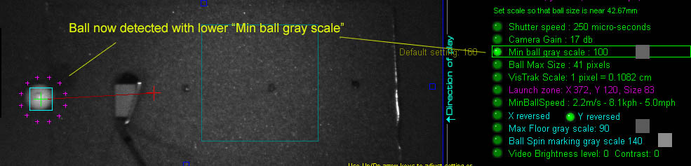
Decreasing the "Min ball gray scale" in the Camera window solves the issue.
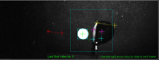
Ball verification check
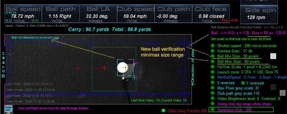
The openCV method of ball detection can sometimes detect the club with the ball if the ball is over over the club face,
so an additional check is now made to see if the result is correct.
Just a simple min / max size check solves the issue. Default min / max size is 30 to 50 pixels in diameter.
Should the test fail (as in the above image), this frame will not be used in any ball speed or ball path calculations.
Note that the new "Suppress Club" feature usually solves this issue too but - as club markings can also cause problems - the min max ball size check should always be made.
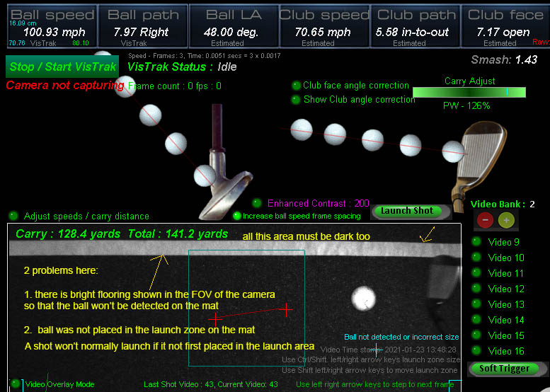
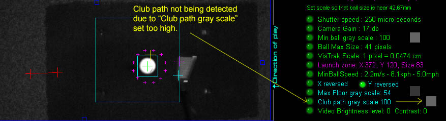
Floor brightness level
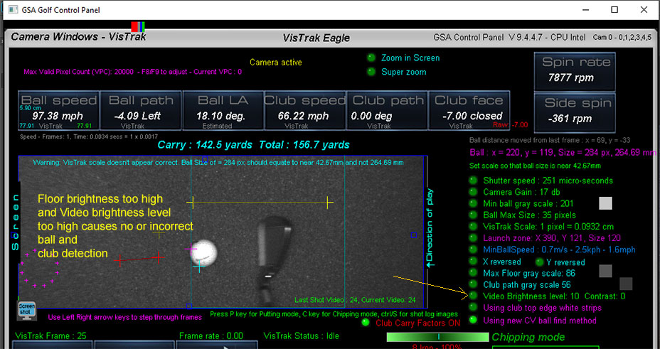
If the floor brightness level is set too high or the floor is too refelective, then the system won't be able to detect the shot.
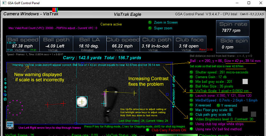
Reducing the "Brightness" and increasing the "Contrast" fixes the problem.
![]()
Enhanced Contrast
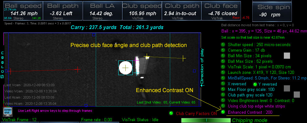
New 1. More improvements to club face angle detection
New 2. The "Suppress club" option is now renamed "Enhanced Contrast"
New 3. When Enhanced Contrast is ON, a check is made to to see that the "Max Floor Gray Scale" and "Club Path Gray Scale" levels are not below 100.
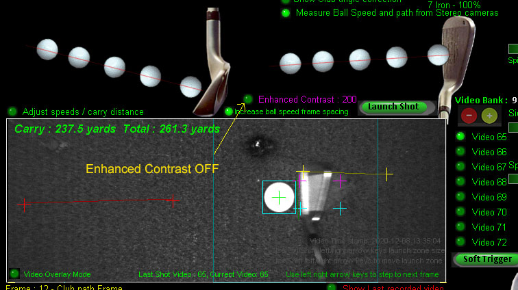
The above is the same shot but without the Enhanced Contrast option on.
![]()
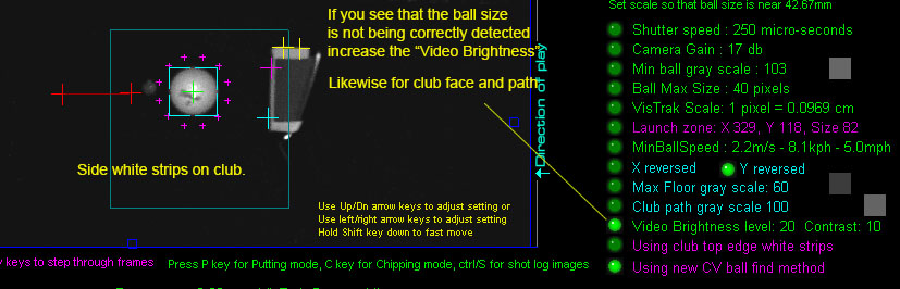
Enhanced contrast option with club track strips
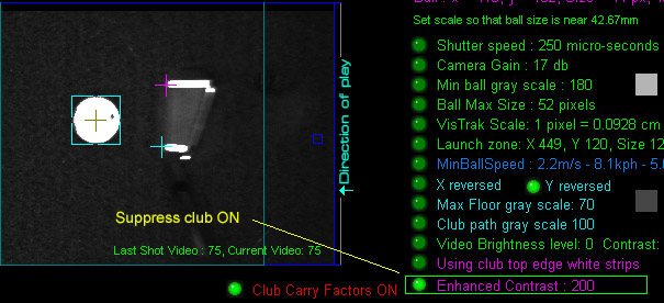
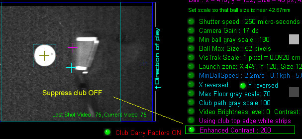
Use the "Enhanced Contrast " feature to accentuate the ball and club markings
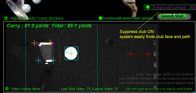
The "Suppress club" option in the VisTrak window too.
Enhanced Contrast option Threshold
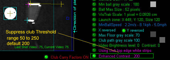
For those that are not using sufficient lighting to illuminate the ball and club tracking strips to the standard gray scale level of over 200,
there is now a new user adjustable "Threshold" level so that balls and club strips that have a gray scale level below 200 are also switched to white.
Note: the "Enhanced Contrast" feature is the same as the old IBS (image background suppression).
IBS switches any pixel brighter than the threshold (e.g. 200) to white and darkens any pixel equal to or below the threshold.
To adjust the threshold level, move the mouse over the option and use the up/down arrow keys.
![]()
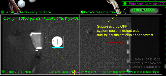
IBS - Image Background Subtraction
VisTrak club detection without tracking dots or strips using IBS ? YES!
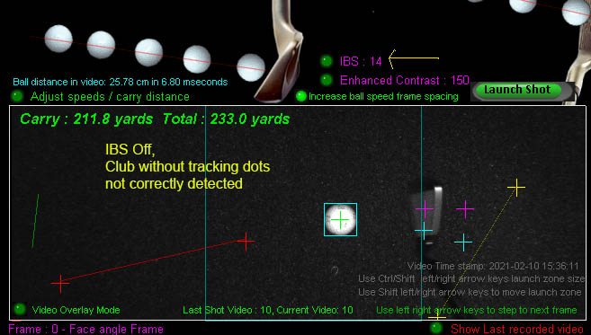
The above image shows what typically happens if the club is dark and tracking dots or strips are not applied to the club.
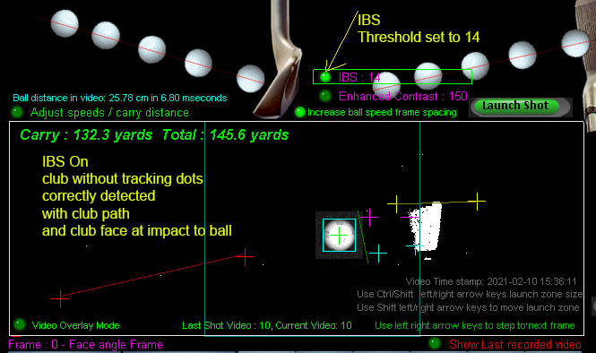
Using the new VisTrak IBS, perfect club face and club path detection. WITHOUT TRACKiNG DOTS !
Not even $10,000 plus systems (like GCQuad or Uneekor) can do that!
You may have to experiment with the IBS Threshold in order to get best results. i.e. with minimum white specks.
I may be able to smooth up the edges later.
![]()
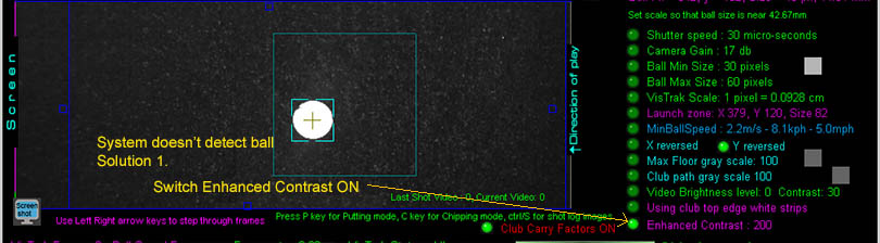
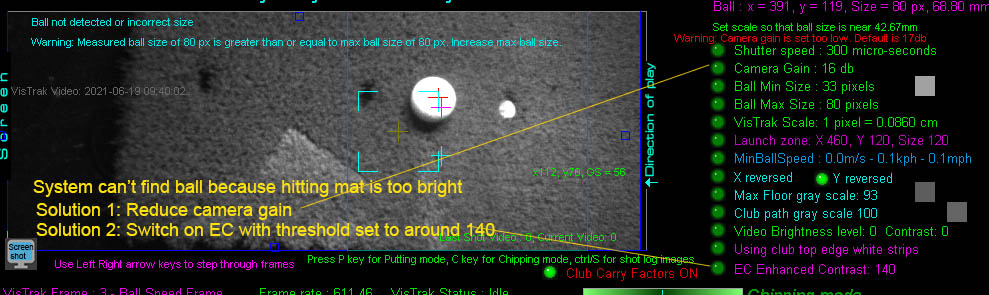
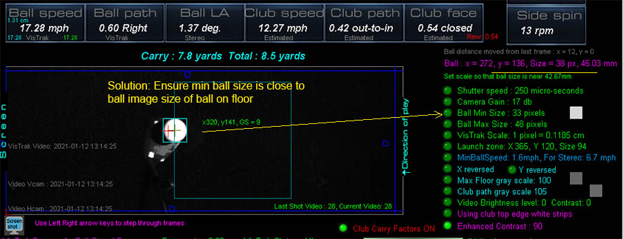
Ball detection issues
What to do if your VisTrak isn't detecting the ball although the ball image is bright
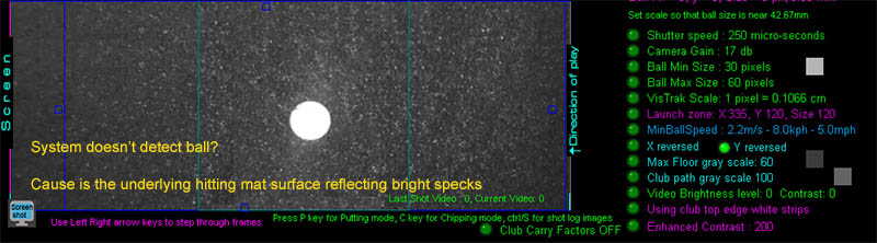
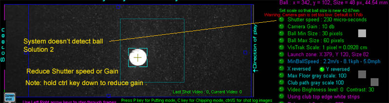
VisTrak IRVC customer issue
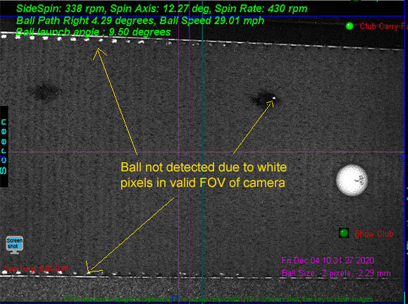
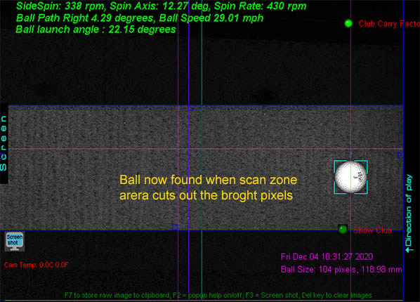
A new customer sent in a shot video showing that the ball is not being detected.
The above images show why and how to correct this.
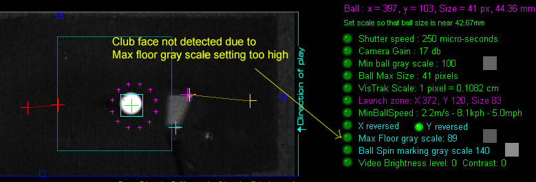
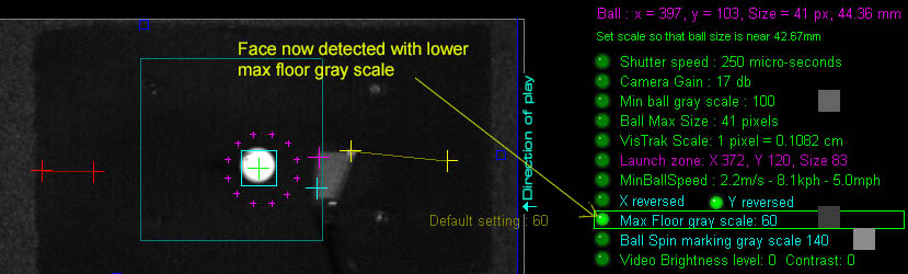
Incorrect ball size detected with reflective mats
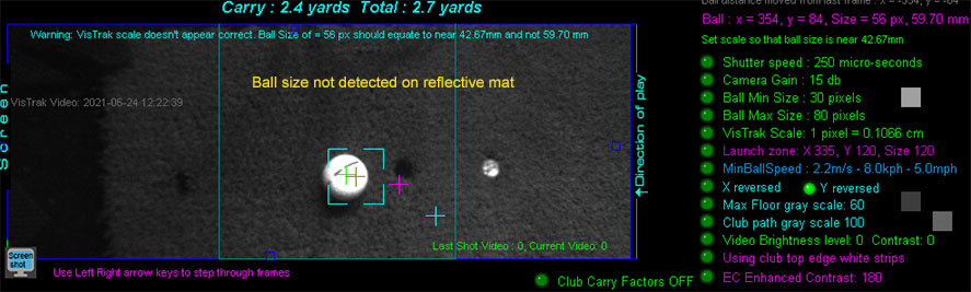
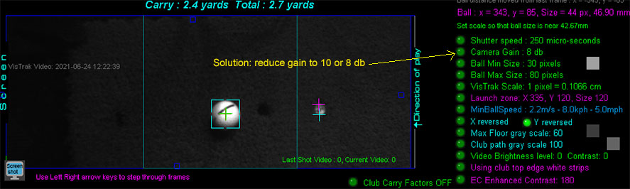
Incorrect "max floor gray scale setting"
If your system detects the ball but immediately launches a small shot even though you didn't strike the ball,
this indicates that the max floor gray scale setting is incorrectly set.
Dark error during "Looking for ball" mode when using high relective hitting mats
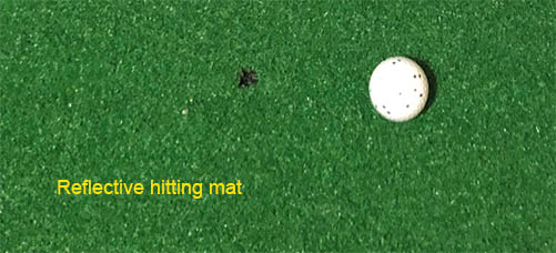
During the "Looking for ball in Launch Zone Area" mode, the system will also want to detect a dark area in front of the ball.
The dark area is used to detect ball strike or movement.
i.e. if the ball was detected on the mat and then the dark area is no longer dark, it will be because the ball was moved or hit and was thus covering it.
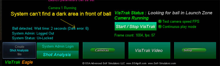
If the dark area is not found, then the system will stay in the "Looking for Ball" mode even though the ball has been detected.
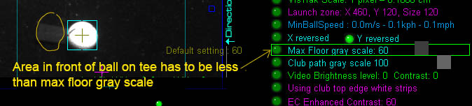
In order for the system to detect the dark area, the area gray scale must be lower than the user defined "Max Floor gray scale".
Ensure that this setting in the camera window is high enough for reflective mats - probably around 60 to 90.
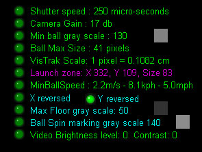
EC (Enhanced Contrast)
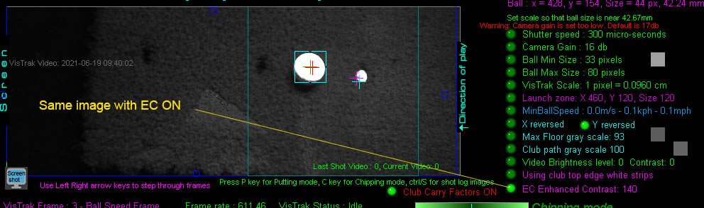
Setting the Max floor gray scale level
Soft trigger to get an image without a ball on the striking mat
The system will calculate the Minimum, Maximum and Average gray scales found in the on the mat.
The Max floor GS level is usually in the 50 to 60 range but you can set it to the calculated Average Floor GS.
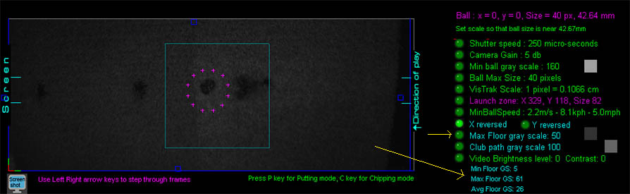
Ball detection
Move the ball to to another position on the mat ahead of the launch zone area and click the Soft Trigger to grab a new image.
If the Max Floor Level is set too low, then the ball won't be detected (as shown above with a floor GS of 40).
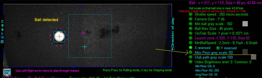
Increasing the Max floor GS level to 50 fixes the problem.
![]()
Fast shots
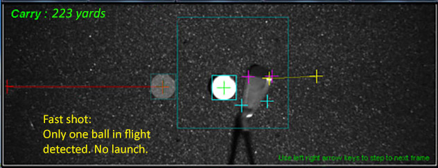
If you find that only one ball in flight is detected with fast shots
move the launch zone area further back to allow more FOV of the ball in flight.
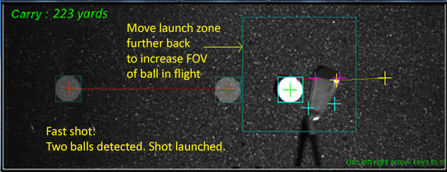
A ball traveling at 200 mph will travel 6 inches in each frame grabbed by the VisTrak camera. (time for each frame = 1/591= 0.00169 seconds)
The FOV after the launch zone in the above image is around 15 inches,
so there's ample space to capture 2 frames of the ball in flight even at the highest recorded golf ball speed of 211 mph
![]()
Other causes of no shot detection
1. The camera is not running or not running at the correct speed
Either incorrect drivers have been installed or there's a cable issue
To confirm that the camera is operational, select the "Video Stream Mode"
or click the "Soft Trigger" button in the Camera window.
You should then see that new images are being grabbed and displayed
Camera speed tests
To confirm that the camera is running at full speed, click the " Test camera speed FPS" button.
After a few seconds, you should see that the FPS rate is at least 590.
Note that the regular speed displayed in the CP will always be around 60 FPS
It is only when the camera is running at full speed - which only occurs after the camera has detected a ball placed in the launch zone -
and the system is ready for the next shot.
In this case there are no screen updates to indicate that the FPS has increased to the full 590 plus range.
The full FPS rate is only shown after the "Speed Test"
Camera running slow
If the VisTrak camera appears to be running at a far slower rate than 590 FPS after the speed test
then check that the camera is connected to a USB3 port on the PC and that the extension USB cable is a powered active USB3 cable.
The VisTrak camera is a USB 3 camera and must be connected to a USB 3 port on your PC.
You can identify a USB 3 port by the SS symbol next to the port
![]()
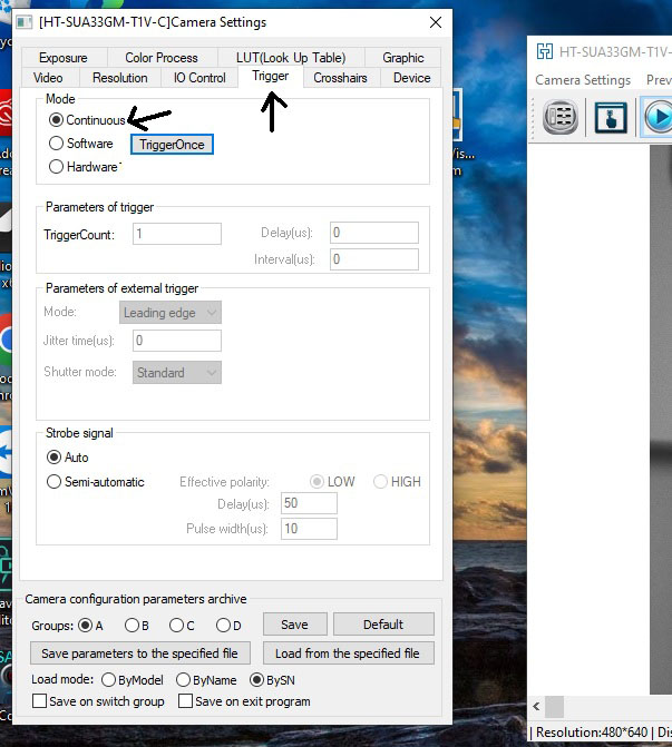
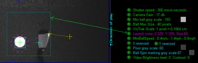
2. The ball was not detected in the launch zone before ball strike
In order for a shot to be detected, the camera must first detect the within the Launch Zone as it's teed up
and - immediately after ball strike - be detected out side the Launch Zone
![]()
3. The camera is not aimed at the ball strike position or its orientation is incorrect.
Direction of play is always from right to left as viewed by the camera.
4. The camera is not connected to the PC using only USB 3 cables
(i.e. USB 2 cables are being used).
5. The camera is not connected to a USB 3 port on the PC
(i.e. it is connected to a USB 2 port).
6. There's insufficient light.
At least a 65w LED visible light video spotlight with lens is required or 4 hi-powered IR LED lights are required.
7. The camera lens is out of focus
Place a ball on the mat, set the camera into "Video Stream" mode and turn the lens dial to focus
8. The game software selected in the Control Panel
does not correspond to the game software running on the PC
e.g. E6 Connect game software is running on the PC but E6 1.6 has been selected in the Control Panel
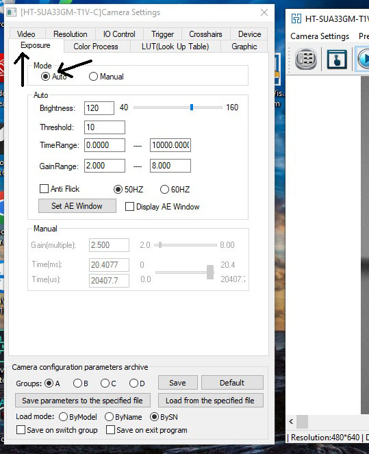
9. The camera settings are not correct
Go to the VisTrak Eagle Installation page to see how to check for these issues
Using just the Control Panel, you should see the following messages displayed for around 5 seconds after a shot
![]()
Club Waggle
Please note: Do not waggle the club over the ball after it has been detected
as this will cause a shadow to be cast over the ball and the system may detect a ball strike.
As long as the ball is not moved out of the launch zone, then no ball will launch in the game software
but the ball detection process will start over again.
In this case - and if the user doesn't notice that the system is again looking for the ball -
and the player makes a shot, then no ball launch will occur.
In addition, the system may - on occasions - detect the club as a ball when waggling over the ball.
In this case, a ball could launch in the game software and the player would have to take a mulligan -
assuming mulligans are allowed of course - or the strike will be valid and count.
Thus, always waggle by the side of the ball and never over the ball.
Practice swings
Once the ball has been detected, do not hit into the hitting surface with practice swings
otherwise the ball may move slightly due to the vibration and then the system will re-enter into the "looking-for-ball" mode.
![]()
2. Club Face detection
![]()
Club not detected
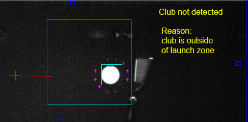
The club - just before ball strike - should always be within the launch zone
Woods and Drivers
As long as the club face is visible to the camera,
there shouldn't be any problems picking up the club face, speed and path with woods and drivers.
Improved club face detection
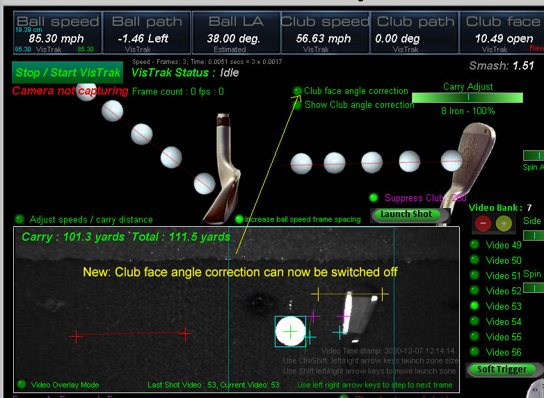
Up until recently, a hard coded club face angle correction was made if the club face compared to the ball path seemed to be incorrect.
The problem with this is that when users look at the video swing playback, they can see that the club face angle is different from what was calculated
and thus assume this is an error or bug in the system.
e.g. The CP may state open club face but the user sees it as closed in the frame images.
For those that don't want this club face angle correction, you can now switch it OFF in the VisTrack window.
In addition, a number of overall improvements were made to the club detection image processing.
Note that it is now recommended to use the "Suppress Club" feature in order to increase the contrast between the club and the underlying surface (as show in the above image).
![]()
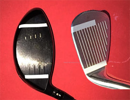
Dark clubs
If a bright face is not visible or the clubs have a dark face,
then a white strip has to be applied to the top leading edge of woods
and the lower leading edge of irons.
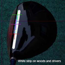
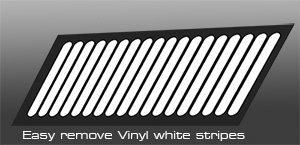
You can make strips from sticky back white photo paper available at Office Depot or Staples stores
Customer Rich G. recommends this method of taping.
![]()
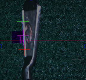
VisTrak - Iron club Top Edge marking
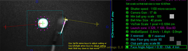
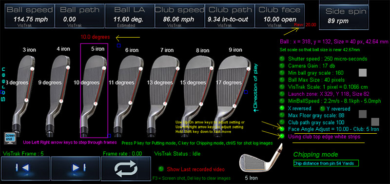
If using iron top edge white strip markings, the measured club face reading from the top edge has to be adjusted to reflect the club face angle at the leading edge.
These adjustments are angles that are subtracted from the measured face angle.
In the above example, the RAW measured club face angle (now shown in red text) was 20 degrees open.
The adjustment for the 5 iron was 10 degrees, so the real club face angle is 20 - 10 = 10 degrees open.
The angle adjustments are user adjustable. Click on the "Using club top edge white strips" then "Face Angle Adjust" options.
Select the club by right and center clicking on the club image. Use the up/down arrow keys to adjust the angles.
Right click on the "Defaults" button to set all club face angle adjustments to their default values.
![]()
VisTrak clubs not being detected
The club - just before ball strike - should always be within the launch zone.
Ensure to move the launch zone and/or place the ball so that the ball on its hitting position is more or less in the center of the launch zone.
![]()
Club reflections with Lob Wedges
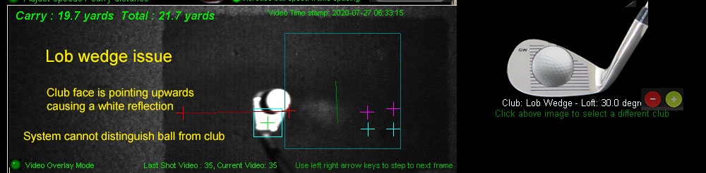
How to solve the Wedge shot issue
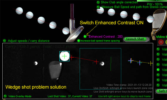
Wedge shots can cause problems when the club is in front of the ball
Switching Enhanced Contrast ON solves the issue.
Issue when club is under and in front of ball
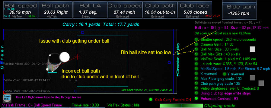
When using very high lofted wedges that get under the ball and cause bright reflections,
the system may not be able distinguish the ball from the club.
While the shot will be detected and launch okay, the video playback may look a little strange.
Unfortunately, there is no (at least no current) solution to this problem.
All other overhead mounted club and ball tracking systems from other manufactures have the same issue too.
Max club face
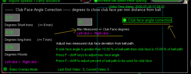
For those that are reluctant to apply tracking dots or white strips to their clubs, you can now set the maximum measured club face angle.
As it cannot always be guaranteed that the VisTrak will correctly detect club face angle without tracking dots or strip markings on the club,
we recommend setting this value quite low in order to prevent wild slices and hooks from incorrect club face angle readings.
BTW all camera club tracking systems on the market today - like the $16,000 GC Quad that requires up to 4 tracking dots to be applied to each and every club -
require reflective markings on the club in order to accurately measure club face angle.
![]()
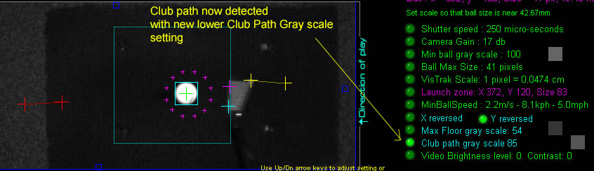
3. Club Path and Speed detection
![]()
4. Ball Speed and Path detection
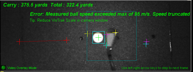
In the above video, the measured ball speed was too high and exceeded the max allowed ball speed of 95 m/s or (212 mph).
![]()
5. Putting and Chipping
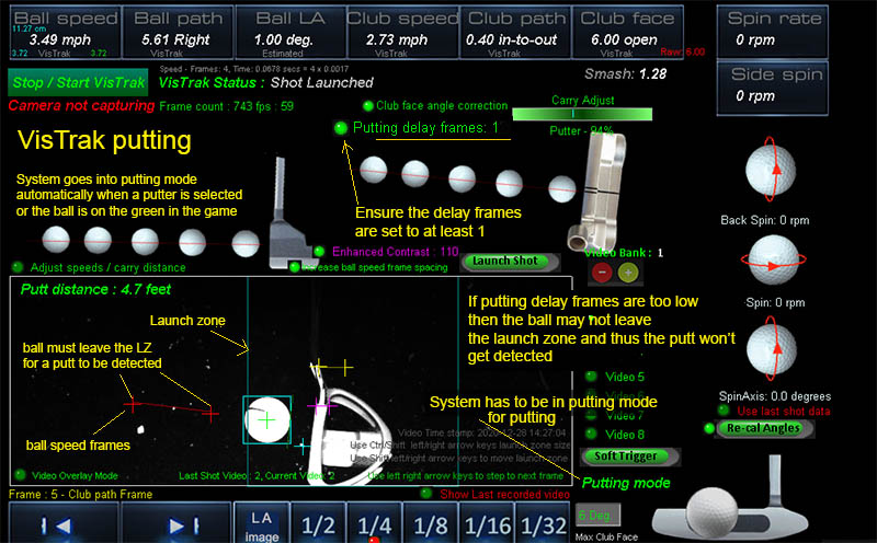
Putting requires that the frame rate of the VisTrak camera be reduced so that images of the slow rolling ball appear in the VisTrak video
In order to do this, the "Putting delay frames" value has to be set. Default value is 15.
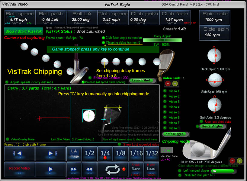
As with putting, the VisTrak camera frame rate should be reduced so that ball images in the frames
are further away from the club and ball images are outside the Launch Zone.
When manually going into Chipping mode or Putting mode using the "C" or "P" keys,
the CP now stops communicating with the game software
so that the game doesn't cause the CP to go back into normal shot mode.
Press any key to restart communication with the game.
Putting and Chipping issues
Most putting and chipping issues reported so far have been due to the player blocking
the FOV of the overhead camera or light with his or head when bending over the ball.
Ensure that the ceiling mounted camera is mounted at least 3 to 3.5 feet ahead of where the ball is being played from
and that you don't block the either the light or FOV of the camera when bending over the ball.
![]()
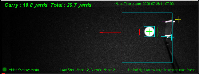
6. Carry distance
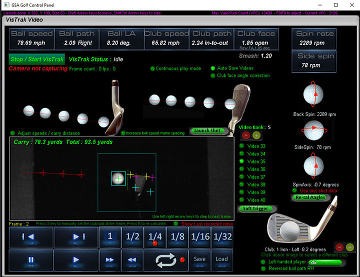
Carry distance is directly related and proportional to the measured ball speed in the VisTrak camera.
The VisTrak camera measures ball speed by measuring the distance the ball has traveled between two two or more frames
and the time elapsed between the frames. i.e. speed = distance / time.
Launch Angle is also taken into account when measuring the distance.
Two red cross hairs in the playback video show where the ball was in the frames that where used to measure the ball speed.
As the camera sees only distances measured in pixels, a pixel to real world units (i.e. cm, meters, feet, inches etc) conversion has to be made.
This conversion is made by the VisTrak Scale.
In the above image, the scale is set to 1 pixel = 0.1082 cm.
Adjusting this scaling factor directly effects the measured ball speed and thus the carry distance of the shot.
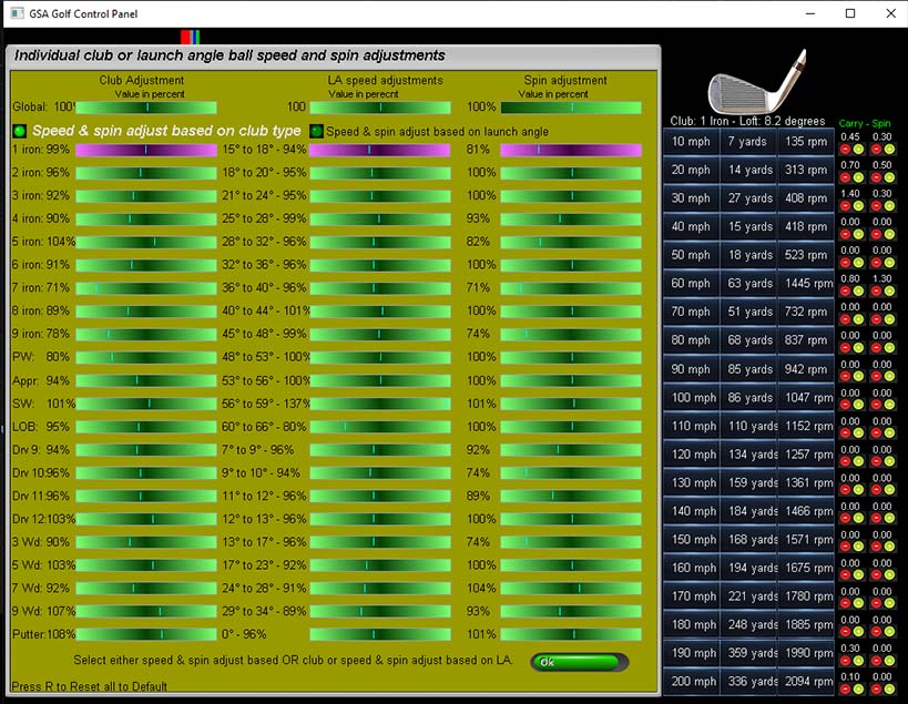
Additional scaling factor and ball spin adjustments can be made for each club in the Carry Factors panel.

In order for these additional carry factors to be used, the "Club Carry factors" option has to be switched ON.
This option is in the Camera window.
Click the "Carry factors" button to open the Club Carry Factors panel.
![]()
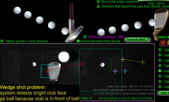
7. Flop shots - ball behind club
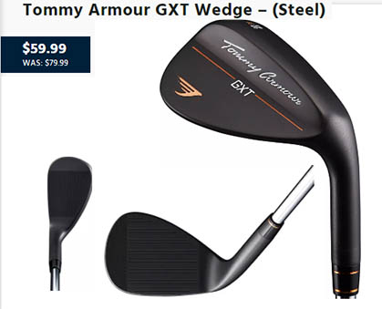
Unfortunately, we don't have a guaranteed solution to this problem at the moment as the system is always assuming the ball is ahead of the club.
If the club is ahead of - or directly under - the ball, and the wedge is wide open and thus reflecting as much light as the ball,
the system will probably mistake the club for the ball.
If the below method doesn't work, then the only guaranteed solution for flop shots is to use a black wedge like in the above image or spray paint the club face matt black.
Wedge shots can cause problems when the club is in front of the ball
Switching Enhanced Contrast ON solves the issue.
![]()
VisTrak lighting options
If you have purchased the VisTrak camera without lighting
then the following is recommended.
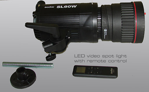
VisTrak LED Spotlight
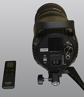
Studio LED video spot light (65w $134 or 150w studio lamp $299)
Click above image to purchase on Amazon
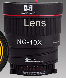
Studio LED spot light lens $54.00.
![]()
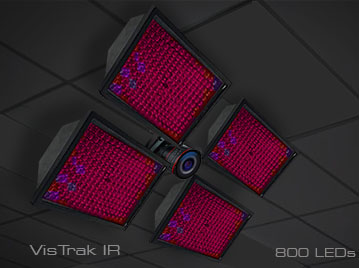
VisTrak IR LED panel
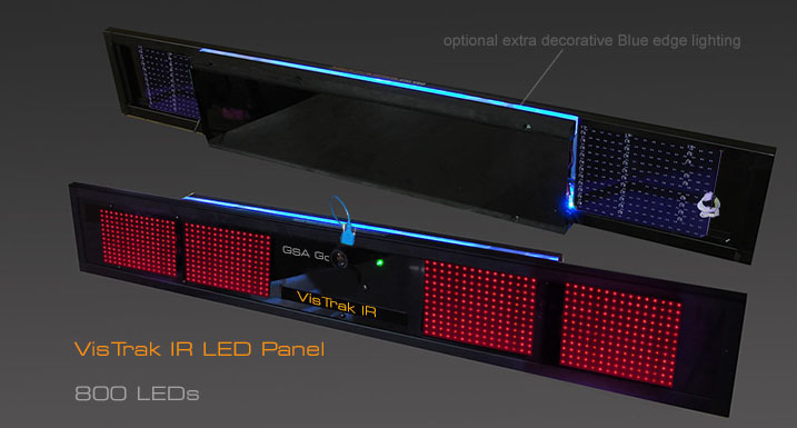
Separate or replacement LED 800 Panel
Note: If purcasing the VisTrak IR this LED panel is already included
$ 999
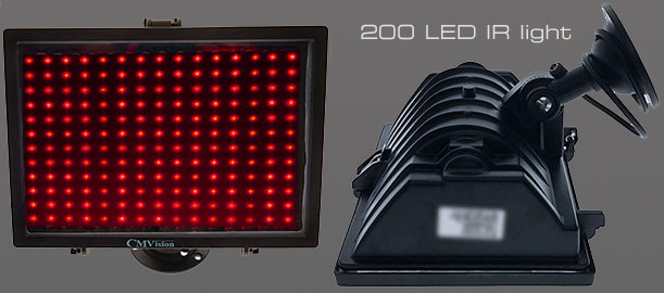
Individual 200 IR LED Lamps suitable for both the VisTrak and Stereo camera systems are available on Amazon.
$ 70 each
At least 4 are required for the VisTrak camera and another 2 for the stero cameras.
Note that these LED lamps are included in the price of the VisTrak Eagle and VisTrak Stereo
8. Connecting to E6
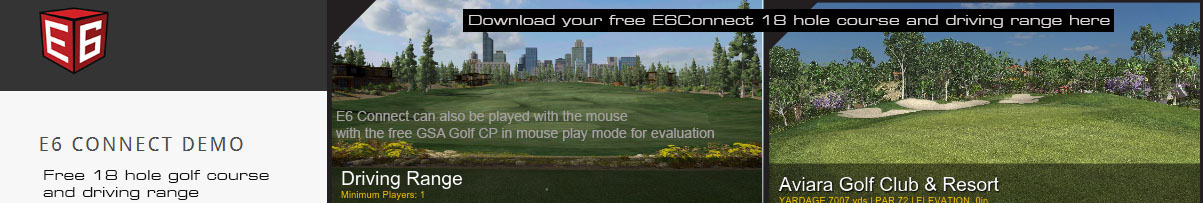
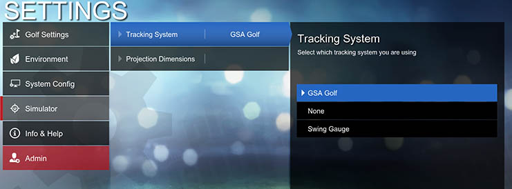
Select GSA Golf in the Settings / Simulator options in E6 Connect
 -
-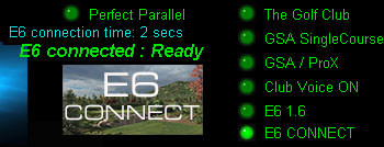
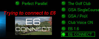
Select E6 CONNECT in the GSA Golf Control Panel's main window
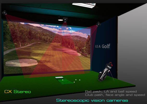
VisTrak Stereo

Recent CP updates
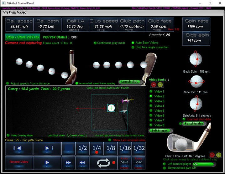
Last data sent to game
When you hover the mouse over the data boxes, the last data sent to the game will be displayed in red text.
Use this to confirm that data being used and displayed in the game software matches this last data sent to it.
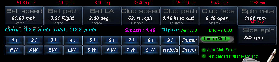
New Data source "Video"
The VisTrak video files include all ball and club data calculated at the time of the shot.
When loading a video, the ball and club data source is shown under the value.

The source name is prefixed with "Vid." when loading a video but you can still see the original data source.

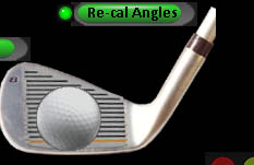
The user can opt to re-calculate the data by clicking the "Re-Cal Angles" button.
When switching from the VisTrak window to the Camera window and then back again, the video file will be automatically re-loaded so that data remains constant.
If the "Re-cal Angles" is activated and stereo images have changed since the original shot
(either by the ball bouncing back or a user retrieves a ball and thus the line scan camera re-triggers the camera) then the results will greatly differ.
Shot Analysis file for CX and PX5 users
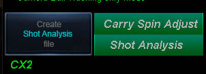
To better support CX and PX5 users, there's now a shot analysis feature that stores the current CX camera images and all the camera settings into a single file.
In case of issues, the user just sends this file to us for analysis.
The embedded camera settings allow us to setup our systems the same as the users.
Fix: when loading the old style videos, the system wasn't calculating club face angle
April 2 1:10 pm
![]() - V 9.3.0.1
- V 9.3.0.1
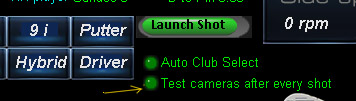
New 1: Auto Club select stays off when switched off while using E6 Connect
New 2: The CP can auto cycle through the test camera procedure after every shot if desired
April 2 10:20 am
![]() - V 9.3.0.0
- V 9.3.0.0
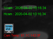
VisTrak Stereo camera time stamps
Image capture time stamps are now shown in the camera panels.
These time stamps should be the same as the video time stamps.
The time stamps are now also embedded in the VisTrak video files.
April 1 11:00 am
![]() - V 9.2.9.9
- V 9.2.9.9
User support: VisTrak Manual Video Record feature
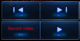
This CP update will includes a manual video record feature.
This feature is for new VisTrak users that are still working on the basics and can't get the system to detect a shot or even detect a ball in the launch zone.
In this case, an automatically generated video will not be produced and thus we can't see what is causing the problem.
i.e. the system will only record a video if a shot has been detected
The new Manual Video Record feature will always generate a video which can then be sent in to us for analysis and thus we can inform the user on how to correct the problem.
![]()
Technical Support


Email and remote access support is available for all original purchasers of GSA Golf systems.
For all non original purchasers (i.e. purchasers of used GSA Golf systems) remote access support can be purchased separately.
Click above images for more information.
![]()

![]()
 Home
Home Products
 Cameras
 Software
 Enclosures
 GSA Courses
 E6 Courses
 Business
 Tech News