![]()
 Home
Home Products
 Cameras
Launch Monitors
Cameras
Launch Monitors Software
 Enclosures
 ProTee
 E6 Courses
 Business
 Tech News
 View Cart
Easy SCX Stereo Camera Calibration
Note that all below instructions assume that you are using CP version 10.0.9.7 or higher
available as of 04/01.2024
Please note: Other than scaling, calibration is only really intended for fine tuning.
If you are experiencing major ball carry discrepancies, then the cause most probably lies elsewhere.
![]()
What is stereo camera calibration?
As each individual camera installation will be slightly different,
(i.e. cameras are mounted at different heights, different spacing, off-line and slightly skewed)
the main objective is to correct the factory set default calibration tables so that they match the particular users camera installation.
This page is mainly concerned with Disparity to ball height conversion.
Camera alignment instructions are dealt with on another page

Click above button to read more...
Super Easy SCX Stereo Camera Calibration
Method 1
This method allows you to calibrate the SCX's stereo cameras with real shots.
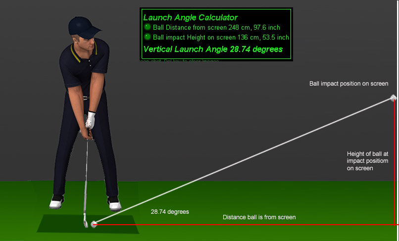
The new Launch Angle Calculator is used to determine the real VLA of the shot and compare it to the CP's measured VLA.
You can then adjust the calibration table to match the CP's measured VLA to the real VLA .
This method of camera calibration is by far the easiest and fastest.
Step 1
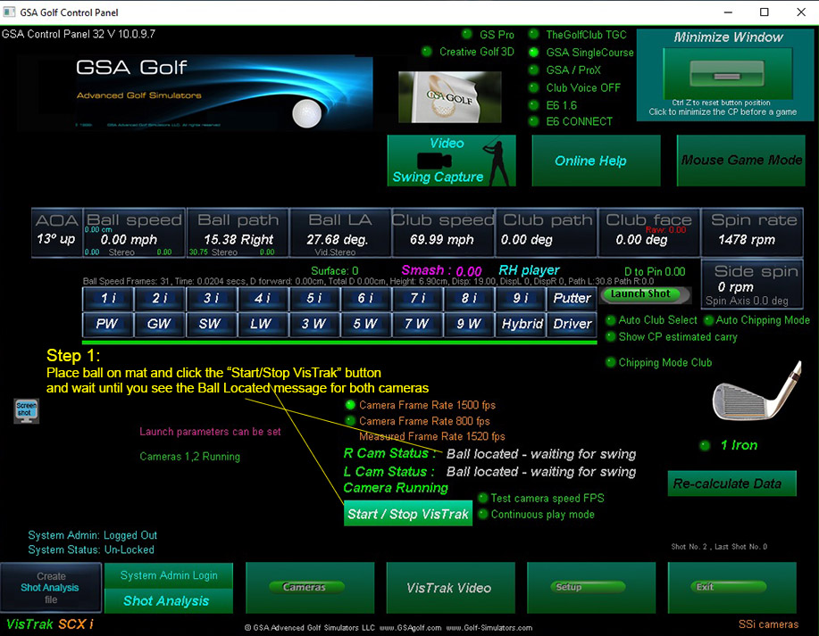
Start the Vistrak cameras in the usual way from the CP's main panel
and place ball on mat.
Measure the ball's distance to the screen.
Step 2
Be prepared to note the ball impact position on the screen and strike the ball
The ball will probably make a temporary indent in the screen after the shot.
Step 3
Measure the height of the impact indent on the screen from the ground
Step 4
Go to the camera panel in the CP and select the "View Calibration Tables".
Step 5
Enter the measured ball distance and height values into the Launch Angle Calculator
Move the mouse over the 2 distance values and use the keyboard's up/down arrow keys to do this
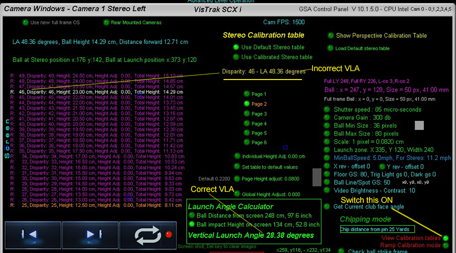
The correct VLA will be displayed
Step 6
Compare the real launch angle from the entered values to the SCX's measured angle
(shown in yellow text next to the stereo disparity value)
If different, use the calibration Page buttons to see the measured Disparity value (shown in white) in the table.
In the above example, the disparity value was 46 (shown on page 2) which equated to a VLA of 48 degrees
Step 7
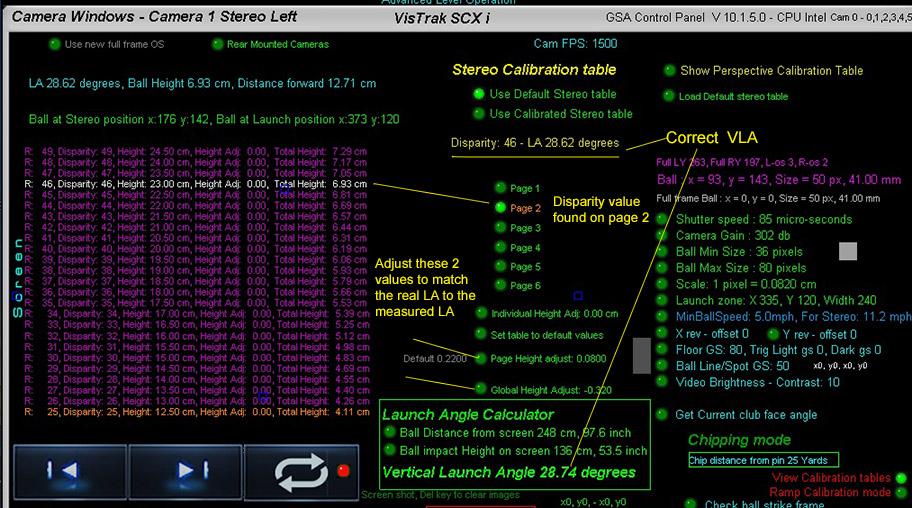
Use either the "Global Height Adjust" setting or the "Page Height Adjust" setting
to match the SCX's measured LA to the real LA.
You can repeat the above procedure using different clubs with various loft angles.
In this case, it's better to use the "Page Height Adjust" setting to match the VLA values
The "Page Height Adjust" only affects calibration values for the 25 rows in the page,
whereas the "Global Height Adjust" affects all values in the 150 row calibration table
Easy SCX Stereo Camera Calibration Steps
Method 2
![]()
Step 1
This sets the ball to ground zero with near zero disparity
![]()
Step 2
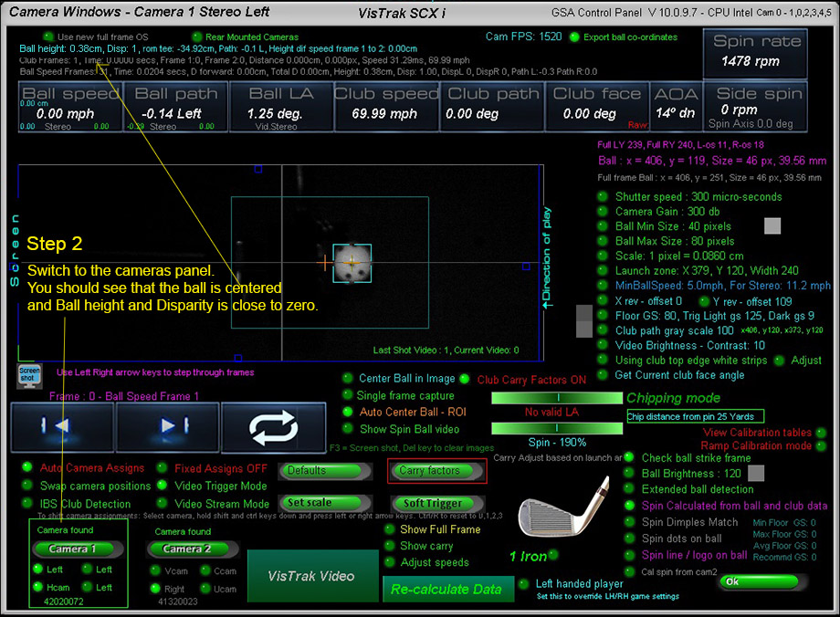
Check to see that the ball is at or very close to ground zero
![]()
Step 3
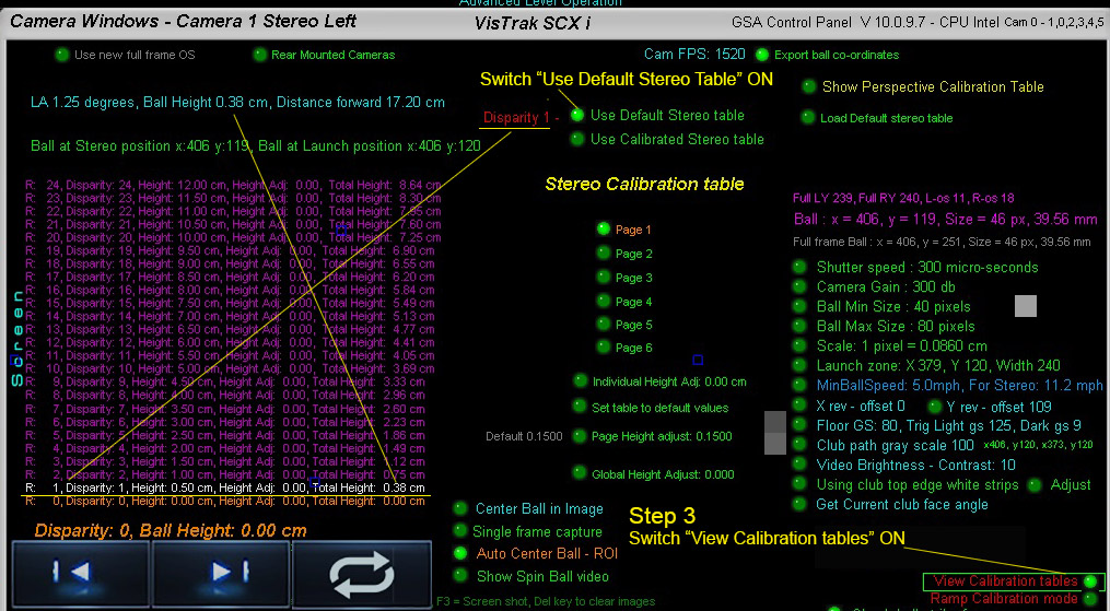
The calibration table is used to convert stereo disparity values to real ball height off the ground
![]()
Step 4
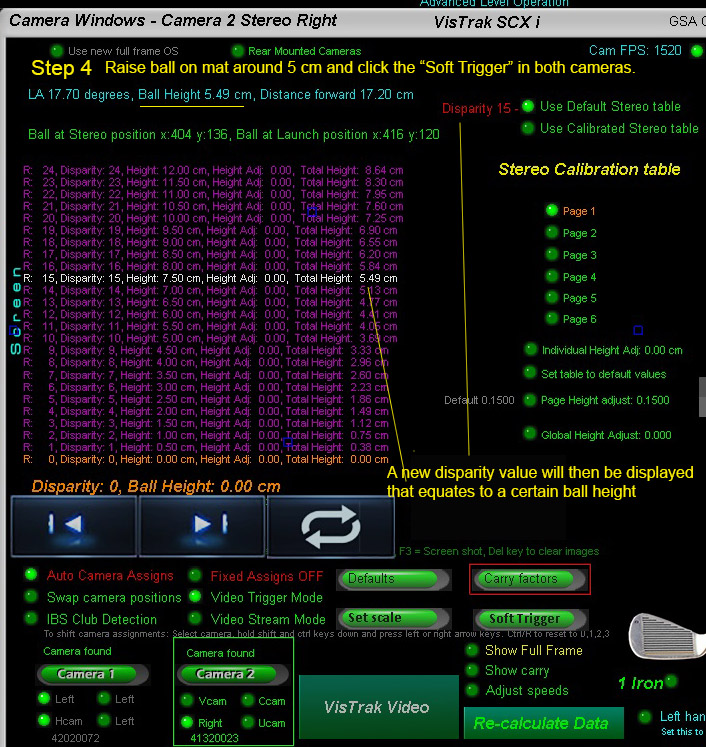
Note: when raising the ball on the mat, use a dark non-reflective object to place the ball on
so that only the ball is detected.
You can use books covered with a dark material to elevate the ball to the desired height.
A black mouse pad is good to cover the books so that only the ball appears bright.
Note that ball height is measured from the bottom of the ball to the floor.
Ensure you click on the Soft Trigger in both the left and right cameras for every height and disparity reading
![]()
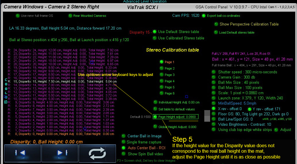
Step 5
![]()
Step 6
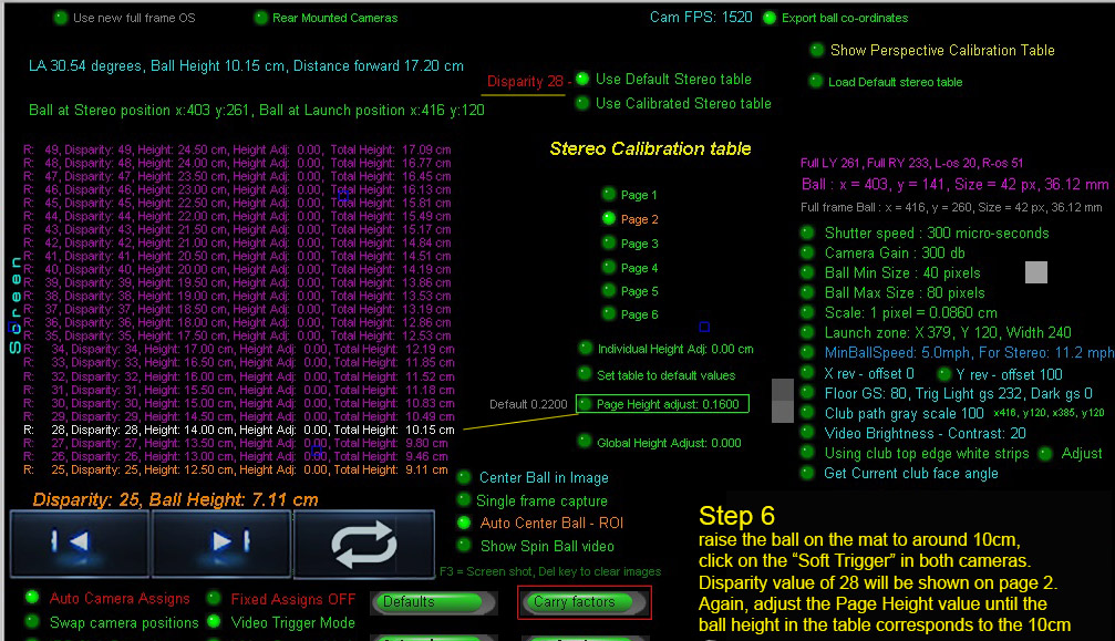
The stereo calibration table has 150 disparity entries that are split into 6 pages.
Each page has its own page height adjust value.
You can also adjust each disparity height value individually but this rarely required
![]()
Step 7
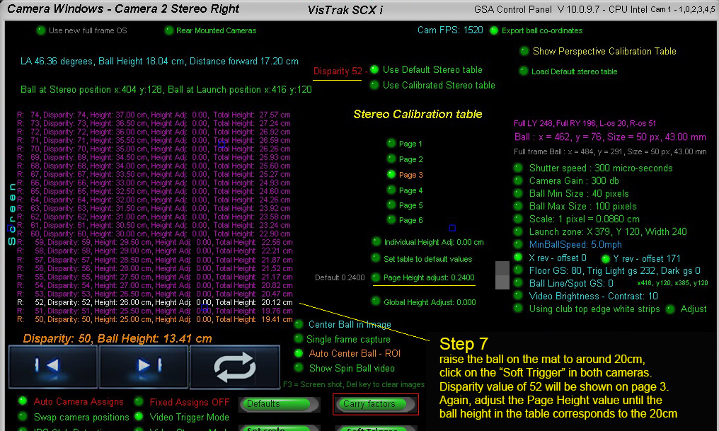
As the SCX camera ball height detection will effectively never go over 27 cm,
there is no requirement to adjust more than the first 3 pages of the table.
Done!
Stereo camera Disparity explained
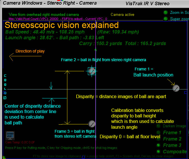
The above diagram explains the basic stereoscopic principles.
If the two 2 stereo cameras are aimed precisely at the center line and a ball is placed at floor level, the images of the will appear on top of each other.
The disparity of the ball is then zero (or near zero) and this is known as the "Converging point"
When the ball is elevated, the images of the ball in the camera frames will start to separate. The distance the ball images are apart is the "Disparity".
Using a "disparity to ball height" table, the exact height of the ball can be determined.
Knowing where the ball was before ball strike the ball LA and path can be determined.
Ball path is simply derived from the divergence the center of the disparity distance is from the center line.
i.e. a perfectly straight shot would show that the 2 ball images are the exact same distance from the center line.

![]()

![]()