![]()

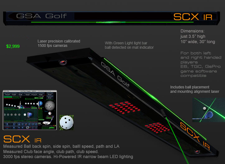
VisTrak SCX Installation
Technical Support


Click the above button to see an easy and fast SCX calibration method
New GSA Golf Quick Guide Owners Manual
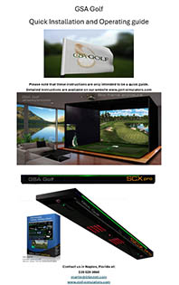
All systems are now supplied with the new quick guide Installation and Operating manual.
If you don't have this, then click the above image to download as a PDF.
For best results, copy to a thumb and take it to a local printing service like Office Depot
and have them print it out on high quality heavy gauge gloss paper - double sided.
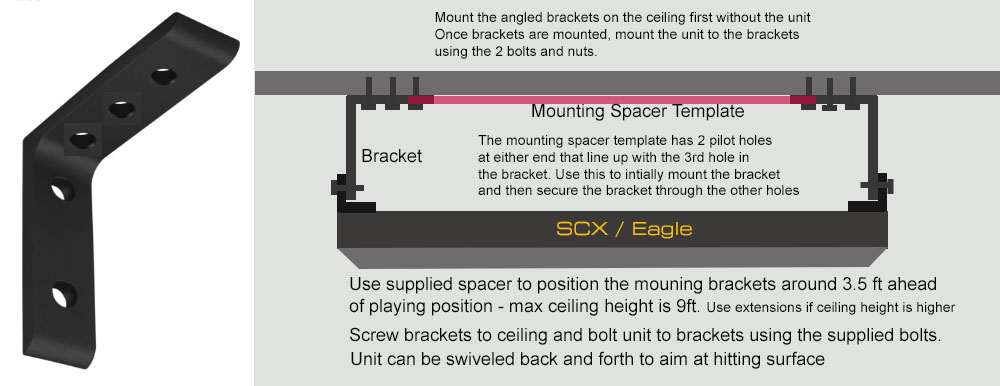
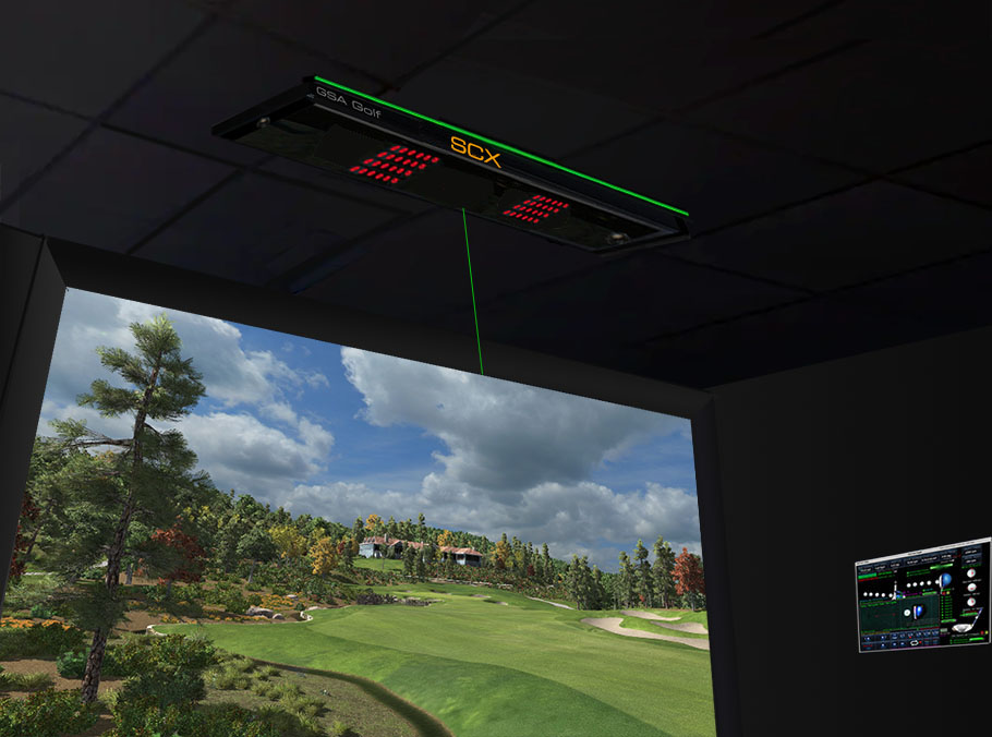
Mounting Instructions
Mounting the cased SCX
Ensure that - when standing back from the unit - the unit is mounted so that the green / white LED strip is at the front and the lettering is readable.
![]()
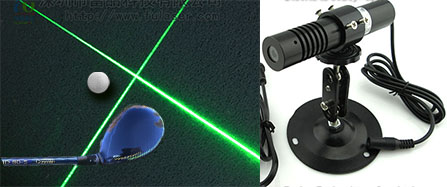
If you purchased the SCX with a laser
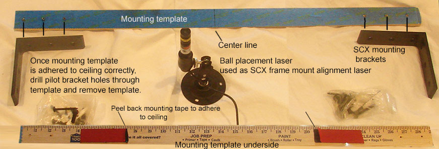
Note: as of 8/11/25 all SCX systems are supplied with a centered plumb line that is attached to the mounting template.
Use this to ensure that the SCX is mounted centered over the ball hitting position center line.
Center plumb line.
Ensure you mount the unit so that it is centered inline with where you will be playing the ball from.
Remove red tape covering from the template stickers and stick the template where on the ceiling you want the unit to be mounted
(usually 3 ft ahead of where the ball is being played from).
Drill pilot holes into the ceiling through the template’s pilot holes. (3 on each side).
Remove template and drill larger sholes to fit the supplied screw anchors.
Remove the large black angle brackets from the unit and screw them into place on the ceiling.
When completed, fit unit back into brackets and adjust the unit’s angle so that it is aimed back at the ball hitting position.
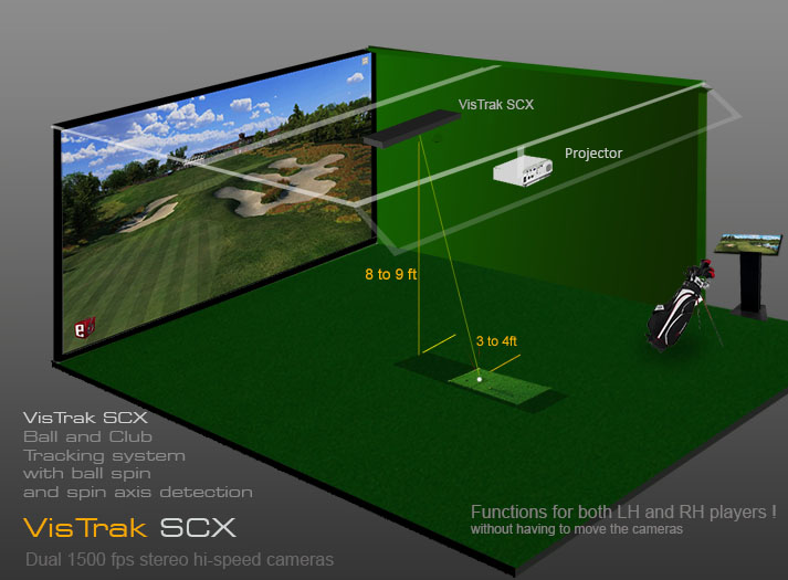
![]()
Max Mounting height should be around 8 to 9 ft
System won't function if much higher.
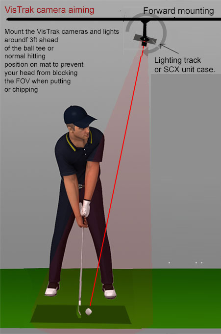
Note that if preferred, the cameras can also be mounted 3ft behind the player.
Tilt unit down so that it points back to the ball hitting area
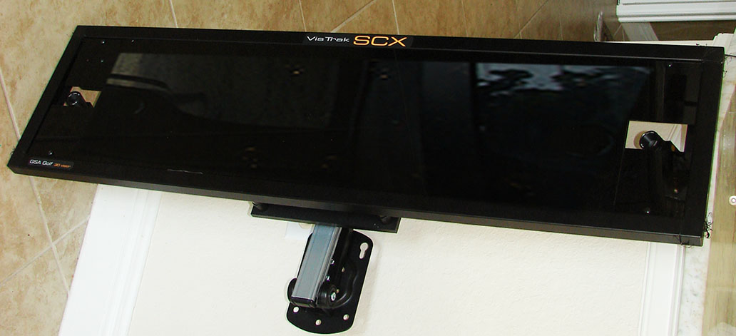
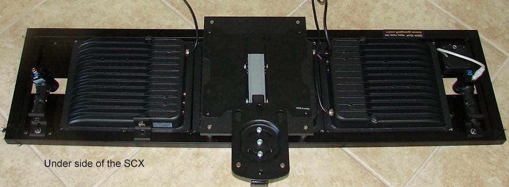
Note: the above 2 images show the SCX with the optional extra projector mount
![]()
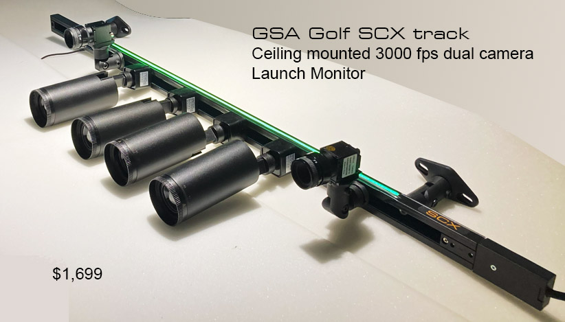
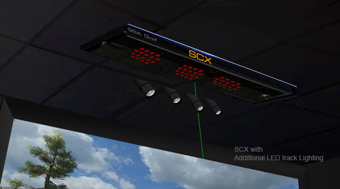
Mounting the SCX Track
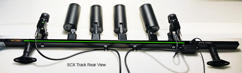
The system is delivered with the lights and mounts folded.
Unfold and aim all lights straight down pointing slightly inwards (as shown above)
Unfold the 2 end mounts as shown above.
Connect the track light power connector to the track with the yellow arrows pointing together.
![]()
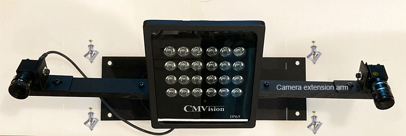
Mounting the cased SCX Compact
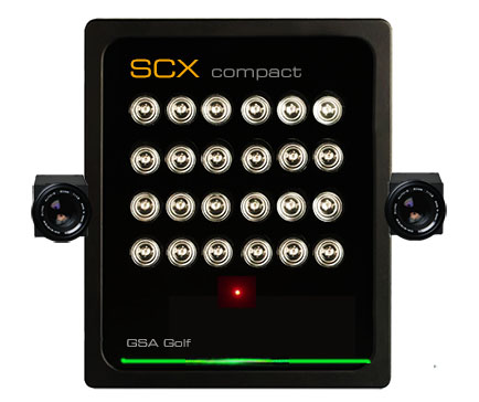
The system is delivered with the optional camera extension arms that significantly increase the Vertical Launch Angle (VLA) accuracy
If you prefer not to use the extension arms, you can remove the arms and attach the cameras directly to the light.
The unit is supplied mounted onto a mounting plate that makes mounting the system on the ceiling easier.
![]()
Camera mounting orientation
Installation Steps
Step 1.
Download and install the Control Panel software from the download link sent to you

Step 2.
Install the camera driver software from the supplied USB drive

Click the above button for detailed camera installation instructions
Step 3.
Connect cameras to USB3 ports on your PC using the 32 ft powered USB3 cable extensions.
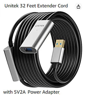
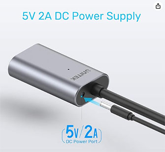
Ensure to connect the power adpater to the cable and plug the power adapter into a 120v power source
Step 4.
Start the Control Panel and ensure that both cameras are running
(i.e. there's no error messages and you see the message that 2 cameras are running)
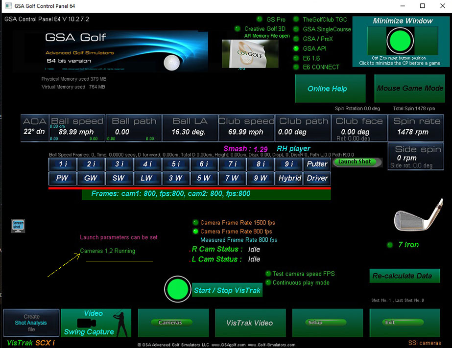
The CP main window
Depending on what system you have, you should see either 1 or 2 cameras are running
If not, then go to

and go to the section
"Using the HuaTeng Vision application to check the cameras"
Step 5.
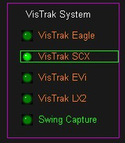
Go to the Setup panel and select Vistrak SCXi
from the list of systems on the right hand side of the screen
Step 6.
Go to the camera 1 panel and right click on the "Defaults" button to set all settings to their default values.
Step 7.
Aiming the unit to achieve equal Light Spread
It is essential that the overhead unit is aimed such that the light is equally spread over the hitting area.
If using a system with invisable IR Lighting (i.e. SCX Pro, SCX compact and SCX Lite),
you can use brown cardboard (use the box that the unit was shipped in for this)
placed over the hitting area to see the light spread with the SCX cameras running in video stream mode.
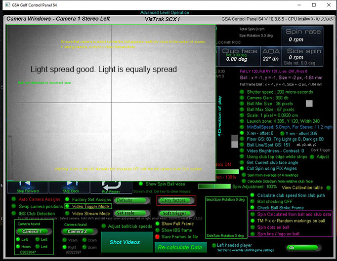
With the unit aimed such that the light is equally spread, then all balls in the hitting area
will appear bright and will be detected
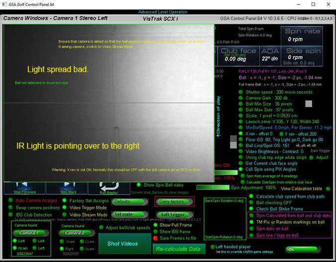
if the unit is aimed away from the hitting area, then the light spread will not be equal
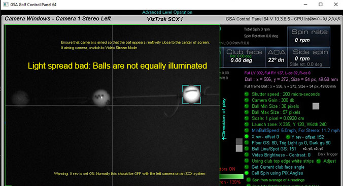
In this case, balls in the center of the FOV of the camera of left of it won't be detected and the system won't function.
Step 8
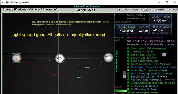
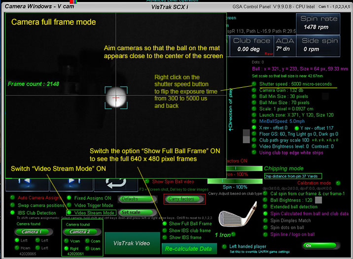
With a ball placed on its normal launch position on your mat,
select the "Show Full Ball Frame" option and the "Video Stream Mode" option and aim the camera so that it appears close to the center of the screen
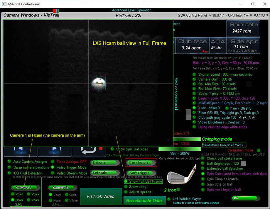
Important!
Only aim cameras when in "Full Ball Frame" mode
Do not try to aim cameras when not in full frame mode
System won't function in this case
Important :
When running the cameras in stream mode, do not have GSpro or TGC or E6 selected.
Select GSA API.
Otherwise the system will constantly try to connect to these game softwares
and will result in the cameras being reset to trigger mode
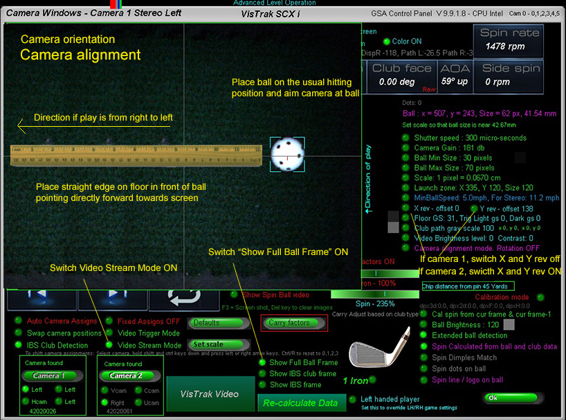
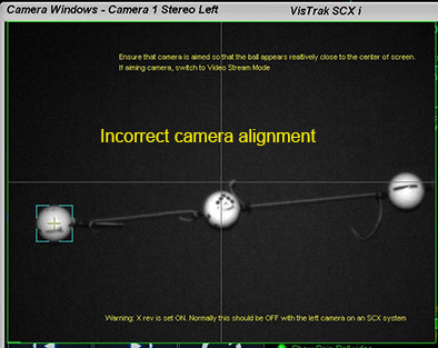
Camera alignment
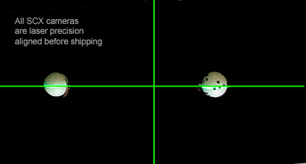
The cameras are factory aligned but due to shipping vibrations they made need some adjustment.
Check your camera aiming
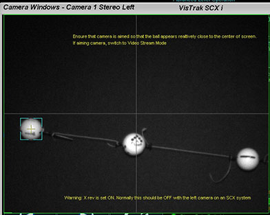
With the "Show Full Ball Frame" and "Video Stream Mode" options switch on in the camera window,
ensure that the ball in both cameras appears approximately in the center of the images as shown above.
It doesn't have to be exact as the cameras will position the ball automatically.
Important!
Only aim cameras when in "Full Ball Frame" mode
Do not try to aim cameras when not in full frame mode
System won't function in this case
Important :
When running the cameras in stream mode, do not have GSpro or TGC or E6 selected.
Select GSA API.
Otherwise the system will constantly try to connect to these game softwares
and will result in the cameras being reset to trigger mode
Step 9.
Do the same for camera 2.
Step 10.
Set the scalling factor
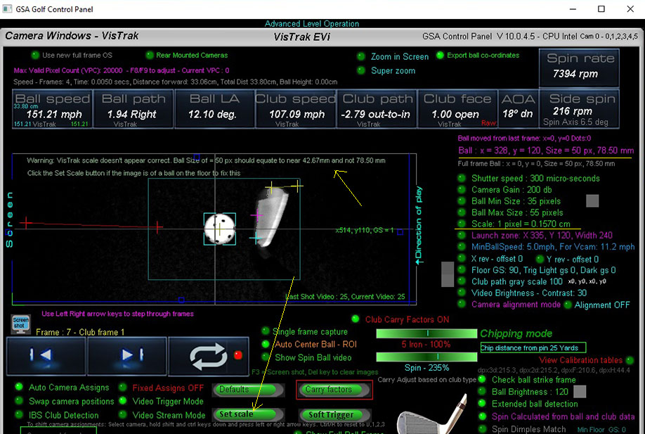
The scaling factor is used to convert distances measured in image pixels (as the camera sees them)
to real world distances measured in cm.
As a reference, the fixed diameter (42.67mm) of a golf ball is used.
To set the scaling factor, place a ball on the mat and click the soft trigger in camera 1 panel.
Ensure that the ball has been correctly detected (as shown above with the aqua blue box lines around it)
and then just click the "Set Scale" button.
The scaling factor is then stored and shouldn't require any more adjustments.
Set the scaling factor as described in the
Step 11.
Click on the Start Cameras button in the Control Panel's main window
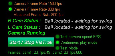
or click the large Minimize button at the top right side of the panel
and wait a second or two until you see the message " ball located, waiting for swing"
You are now ready to play the ball
Note: if you don't see the Minimized CP after clicking on the Minimize Window button,
press the ctrl / Z to restore its position to the top left hand corner of the monitor screen
Step 12.
after a ball strike, you should see the message "Ball launch detected. Launch parameters sent to the game software"
Step 13.
Start you golf game software (E6, GSpro, TGC, CG3d or GSA Golf) and click the large minimize button at the top right of the screen .
You are now ready to play a round.

Cased version
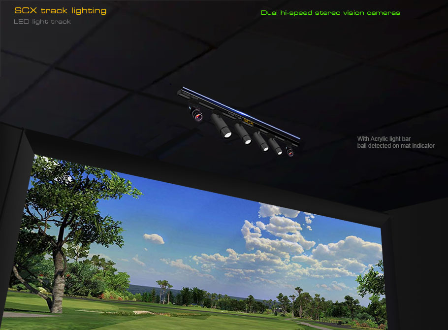
Using the supplied LED lighting track to the SCX vastly increases image brightness.
![]()
VisTrak camera setup videos
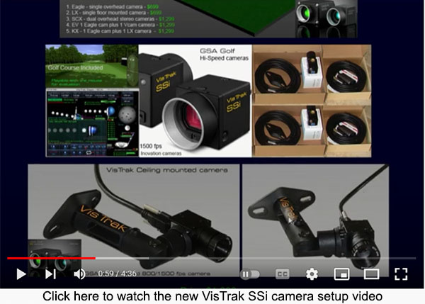
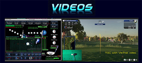
Click above image to view all VisTrak setup YouTube videos
![]()

Click above button to read
![]()
Fault finding and Issues
![]()
Installing the Control Panel software
Follow the download links sent to you via email
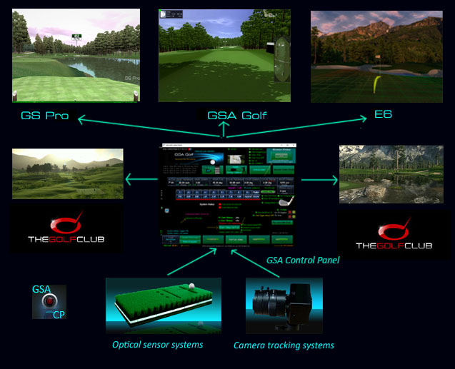
The GSA Golf Control Panel (CP) interfaces the cameras to the game software
and performs all the camera image processing to calculate the shot data
Error message when first starting the CP ?
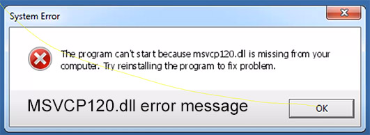
If you see the above error message when first starting the Control Panel (CP)
then your PC requires the VC Redistributable files.
Click on the above image to see an installation video
Download VC redistributables hereHere
![]()
GSA Golf system minimum PC requirements
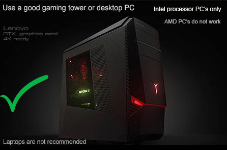
Intel i5 or above Processor with a desktop gaming PC
Warning! Do not use PC's with AMD processors or low cost Laptops!
Warning! Do not use custom made PCs
Only use stock PC's
i.e. those that are available on Amazon in the $1,000 to $1,500 plus range
Our experience over the years has shown that the USB speeds with
custom made PCs do not meet the camera USB requirements.
8GB RAM Nvidia 1070 Graphics Card or equivalent
25GB of Hard Drive Space
Windows 10 or 11 (Required)
Internet Connection
(Required if using 3rd party game software such as E6, TGC or GSPro)
2 x USB3.1 or 2 x USB3.2 ports (Required)
Note: The cameras are USB3 cameras
and will only run at the correct speed when connected via USB3 cables directly to separate USB3 ports on the PC
Warning
If using 2 cameras, do not connect the cameras together with a Hub !
All cameras must be directly connected to separate USB3 ports on the PC
Use only the supplied powered USB3 extension cables
![]()
Warning! Do not use older PC's that have been modified in anyway
(i.e. new mother board, additional USB3 cards etc)
Experience has shown that the high-speed cameras do not function with such older or modified PCs
![]()
SCX wiring
2 X USB3 ports (Required)
Note: The cameras are USB3 cameras
and will only run at the correct speed when connected via USB3 cables directly to separate USB3 ports on the PC
Warning
If using 2 cameras, do not connect the cameras together with a Hub !
All cameras must be directly connected to separate USB3 ports on the PC
Use only powered USB3 extension cables if the supplied cables are not long enough
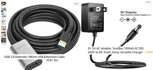
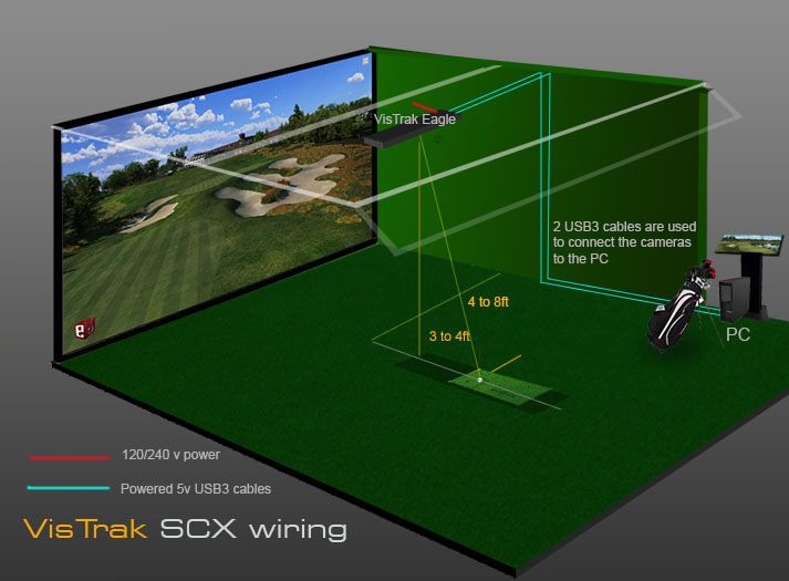
Run the 2 USB3 5v powered cables as shown in the above diagram to the PC
Max length of USB3 cables with extension is 40 feet with powered USB extension cables.
Main power is 110v/240v
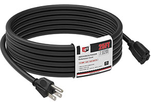
Power strip and 25ft power extension cable included
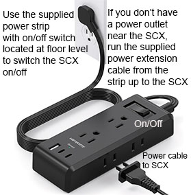
As an on/off switch on the SCX unit itself would require the user to get on to a step ladder everytime to switch the unit on/off,
we supply a floor level power strip with an on/off switch with a 25ft power extension cable to the unit to switch the unit on/off.
![]()
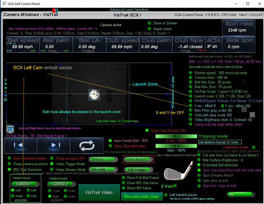
Default CP SCX Left camera panel values
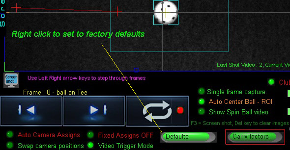
Right click on the "Defaults" button
to set all values to their defaults
X and Y rev options must be set OFF
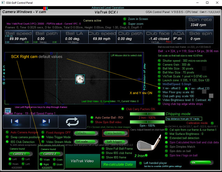
The CP SCX Right camera panel
X and Y rev options must be set ON
Right click on the "Defaults" button
to set all values to their defaults
![]()
Camera Alignment
Please note:
As of August 2024, all SCX systems are shipped
with laser precision pre-calibrated fixed camera alignments.
All SCX cameras are factory laser precison aligned before shipping now.
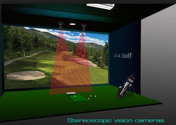
![]()
SCX stereo camera aiming and alignment

![]()
The SCX Control Panel
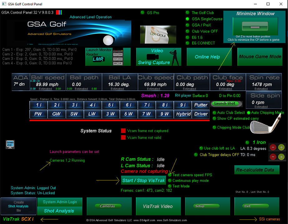
The CP main window
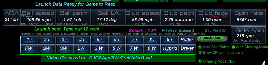
After a ball valid strike, the CP will show the Launch sent message
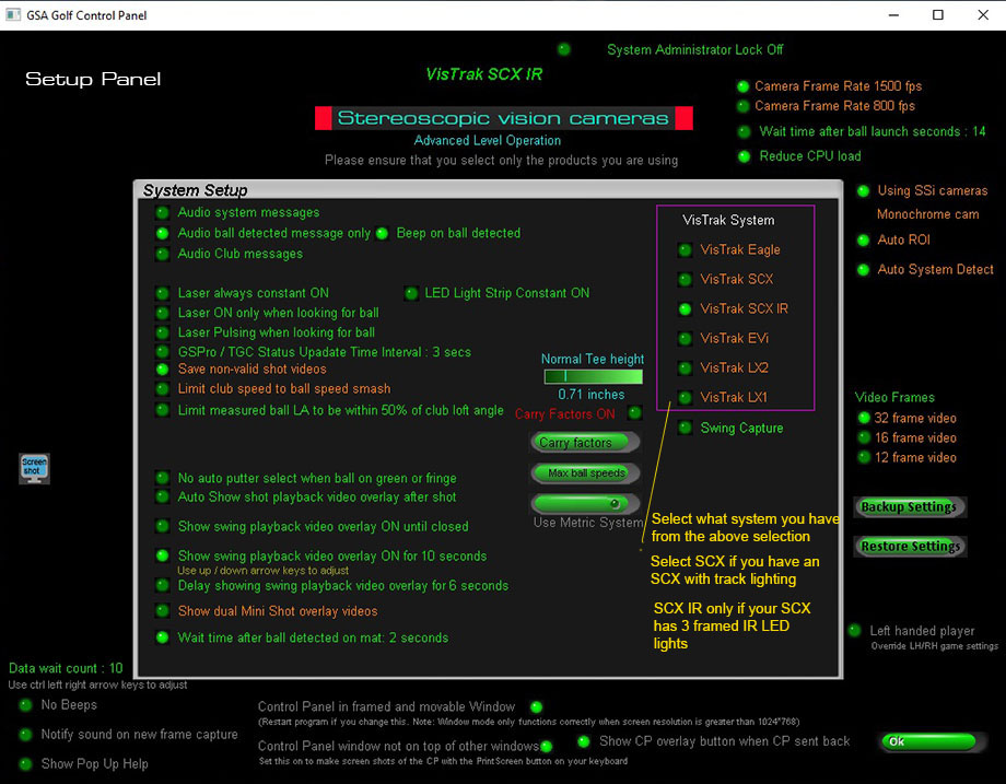
The CP setup window
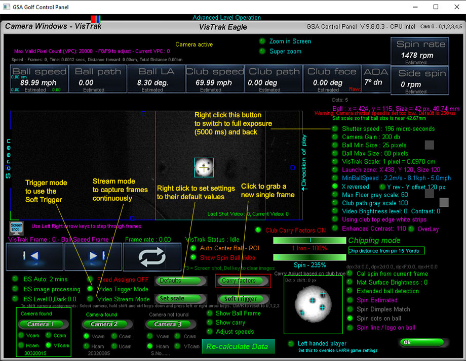
The CP Camera window
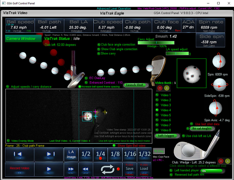
The CP Shot Video window
![]()
Lens focusing and aiming
It's important that the camera lenses are in focus.
The lenses are pre-focused before shipping though.
To focus, place a ball on the center line of the enclosure and point the camera at the ball.
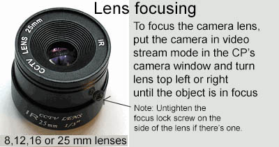
Switch to "Video Steam Mode" in the CP's camera window so that you see the captured images.
Rotate the outer dial on the lens in or out until you see that the ball is in focus.
![]()
SCX Vertical Launch Angle calibration
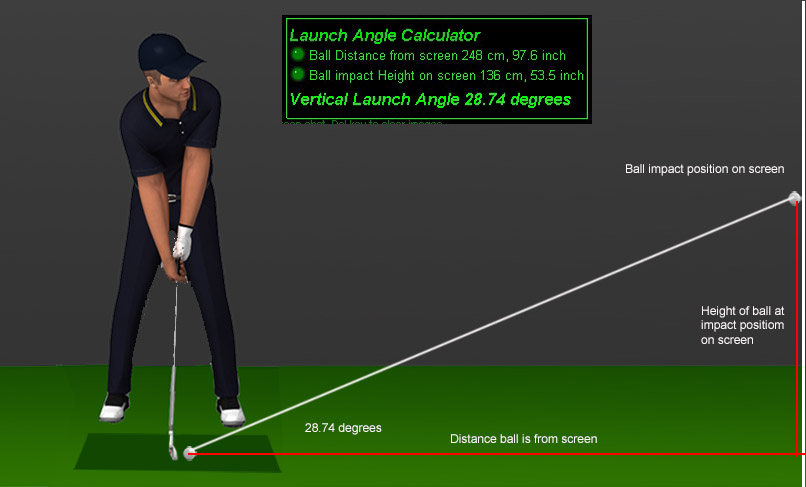
Click the above image to see how to calibrate the SCX's cameras to measure accurate vartical launch angle
![]()
VisTrak vs GC2 comparison results
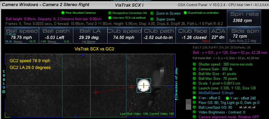
Just in from independent tester Phil in the UK that has a GC2 and is running comparison tests with his VisTrak system
Putting
Vistrak 12.99 mph, GC2 13.0 2 mph
Vistrak 6.36 mph, GC2 6.0 3 mph
Vistrak 16.5 mph, GC2 17.3 mph
Chipping
Vistrak 49.73 mph, GC2 49.2
Full shots
Vistrak 80.37 mph , GC2 78.9 2 mph
Vistrak 78.63 mph , GC2 79.8 3 mph
Vistrak 87.22 mph, GC2 88.0 mph
![]()
SCX Calibration
Camera alignment
To check and adjust camera alignment
place a ball on the usual hitting position on the mat.
Then place another ball directly behind and another ball directly in front of the center ball
spaced at around 6 to 8 inches apart.
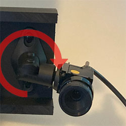
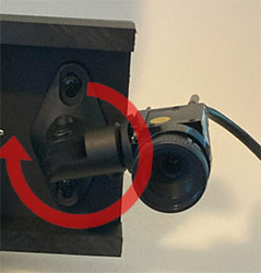
Rotate the camera on its base to adjust camera algnment
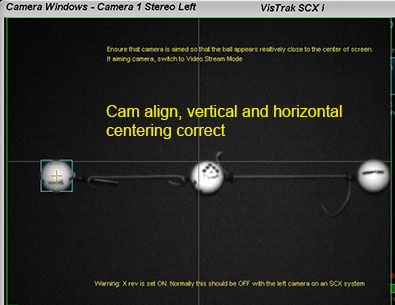
All 3 balls should appear on the same horizontal line
![]()
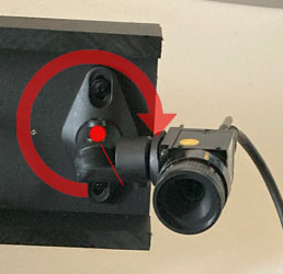
Vertical ball centering
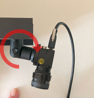
Rotate the camera inwards and outwards to position the ball images onto the center line
![]()
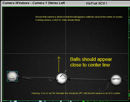
Horizontal ball centering
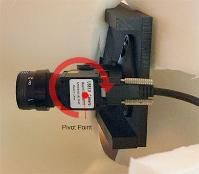
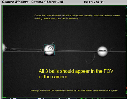
Rotate the camera up / down to position the ball images so that they all appear in the FOV of the camera

Click above button to read more...
![]()
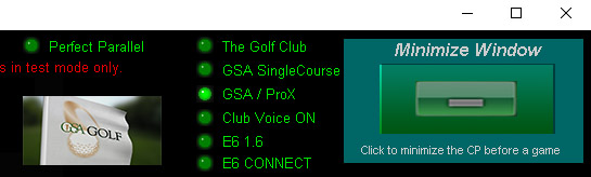
VisTrak Golf Game Play
VisTrak interfaces with TGC (The Golf Club), GSA ProX, GS Pro, RedChain, E6 1.6 and E6 Connect golf game software.
Select the game software you are using from the radio buttons at top right corner of the Control Panel's main window.
Click the large "Minimize Window" button to start the cameras and connect to the game.
After Clicking the large "Minimize Window" button in the CP,
2 small buttons will show at the top left hand side of the game software.
Click Control Panel to go back the CP
Click Show Swing Video to see the last shot video
![]()
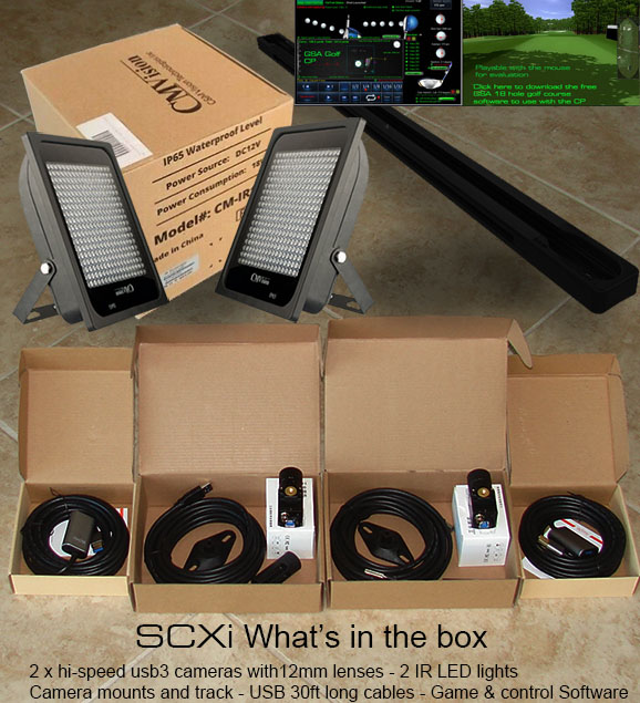
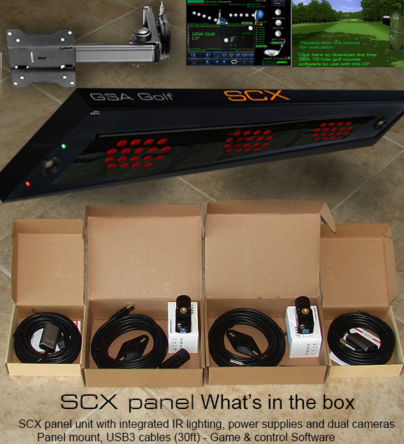
SCX Panel
![]()
SCX Lighting
If you have purchase just the cameras, the following IR lighting is required.
IR LED Lighting

CM Vision IRP24-850nm LED IR Array Illuminator
Min 3 required for ceiling mounted SCX and Eagle systems
Max mounting height is 9ft
Note that the power supplies are not included when purchasing on Amazon
You will require 5 amp 12v power supplies for this IR Illuminator
![]()
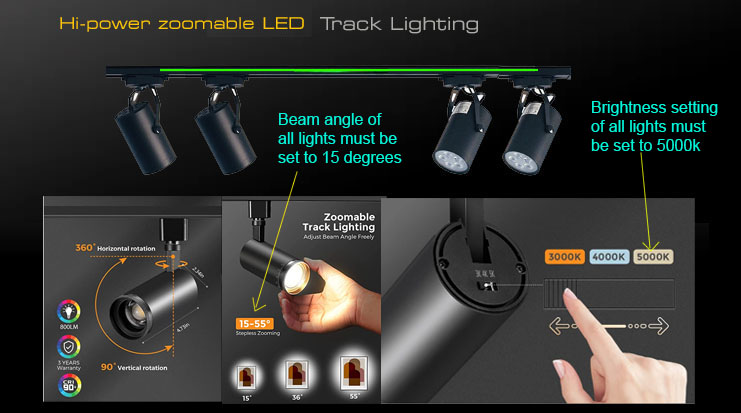
Track Lighting
Instead of expensive IR LED lighting, you can also use LED track lighting.
All lights have to be set to 5000k
![]()
Recommended items when purchasing your own halogen track lights

Track fixtures must feature built-in 110v to 12v transformers
Improving Ball detection using camera "Contrast" settings
New camera image and brightness controls that turn low light dull images of the ball and club into vibrant bright images.
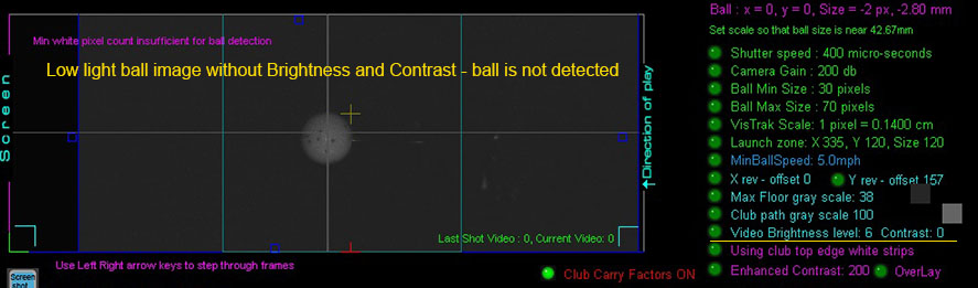
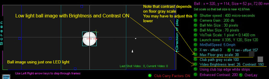
Click above images to read more about camera ball detection and Contrast settings
LED Track Lighting Track
4 hi-power LED zoom-able track light system with 800 Lumens per light
With track
Price $199
![]()
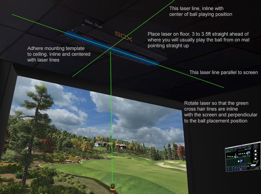
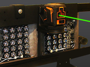
Laser setup
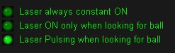
Place ball on the usual position on the hitting mat.
Switch to "Laser always constant ON" in the CP's Setup panel.
Manually aim laser to point at the ball.
Switch back to "Laser ON or Pulsing when looking for ball"
![]()
SCX ball Spin
If you prefer measured ball spin instead of calculated ball spin, then spin dot balls or Taylor Made Pix balls will be required
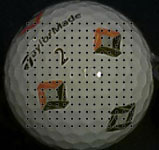
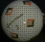
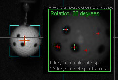
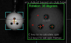

Note that only well defined and spaced spin dot balls can be used ( as hown above).
A maximum of 4 dots should only be visible within the center area of the ball.
Also note that camera exposure time (i.e. shutter speed) has to be set at or below 150 micro seconds and frame set to 1500 fps.
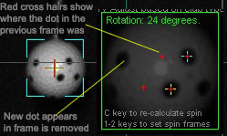
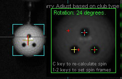
Ball Spin Setup
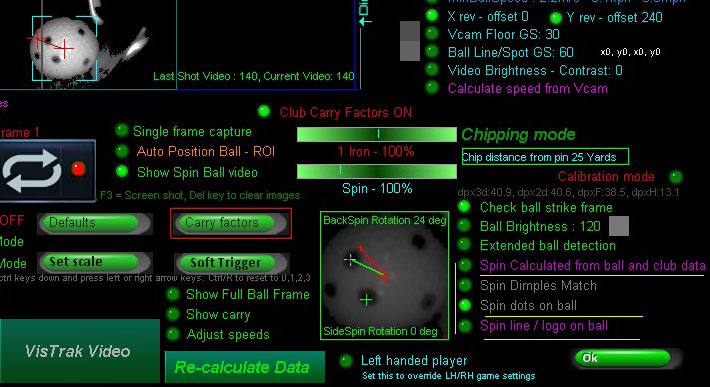

Click above button to read how setup ball spin detection
![]()
VisTrak Golf Game Play
How to play a golf game with the system
VisTrak interfaces with TGC (The Golf Club), GSA ProX, GS Pro, RedChain, E6 1.6 and E6 Connect golf game software.
Select the game software you are using from the radio buttons at top right corner of the Control Panel's main window.
Click the large "Minimize Window" button to start the cameras and connect to the game.
Start your golf game application.
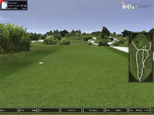
If you haven't already purchased any game software, you can use the supplied GSA 18 hole golf course demo software.
In this case, select the GSA Single Course radio button.
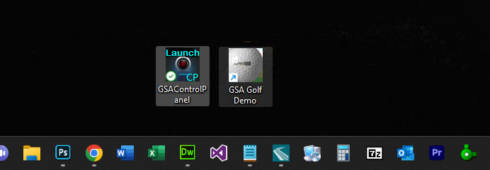
Then click the GSA Golf Demo icon from your PC's desktop

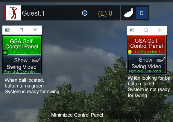
After Clicking the large "Minimize Window" button in the CP,
2 small buttons will show at the top left hand side of the game software.
The system will then start to look for a ball in the Launch Zone area. The top button is then red.
Once a ball has been detected in the Launch Zone area, the button turns green indicating that the system is ready for the swing.
Note: Click "GSA Golf Control Panel" button to go back the expanded CP's main window
Click Show Swing Video to see the last shot video
Note that the ball must always be placed in the launch zone area in order for it to be detected
Once the ball has been detected in both cameras, the system is ready to capture a ball strike and send the data to the game software in order to launch the ball.
Ball strike trigger pixels
![]()
An error message is now (as of CP version 9.9.4.0) shown in both the CP's main panel and camera panel if the dark ball strike trigger pixel is brighter than the user defined floor GS level.
System is unplayable in this case as the ball will launch immediately after placing it on the mat.
It's important to know that the forward pixel (i.e. the pixel in front of the ball) must be darker than the "Floor GS" and that the
Trig Light pixel (i.e. the pixel in the center of the ball) be brighter than 150 GS (Gray Scale) otherwise a ball launch will immediately occur.
A ball strike is detected when either the dark pixel goes light (i.e. the ball flies or rolls over it) or when the Light pixel goes dark (i.e. because the ball is suddenly not there anymore).
If you find that a ball launch occurs immediately after placing the ball on the mat, ensure the dark GS pixel is shown darker that the Floor GS. If not, increase the Floor GS so that it is lighter than the dark pixel.
In the above error example, the Trig Light pixel shows a GS of 234 (i.e. over 150) but the dark pixel GS is 14 (i.e. brighter than the Floor GS of 11)
SCX Limitations
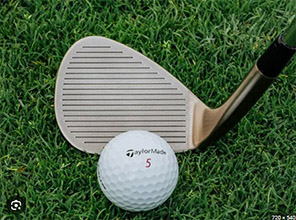
Currently, it cannot always be guaranteed that small chips with bright faced wedges will be detected.
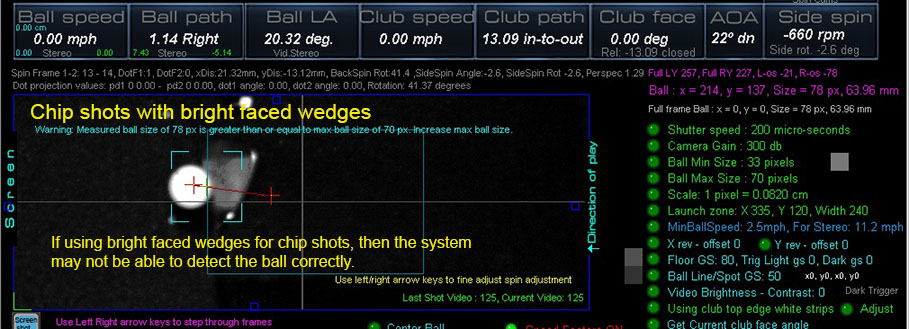
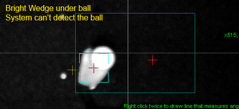
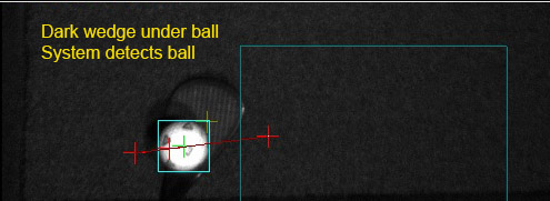
If the issue persists, you'll have to use dark colored wedges or apply the supplied sticky back matte black stickers to the wedge face.
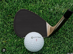
Above image showing how the wedge looks when the wedge black sticker is applied
Just email us with your address for your free black wedge stickers pack if you didn't already receive them
![]()
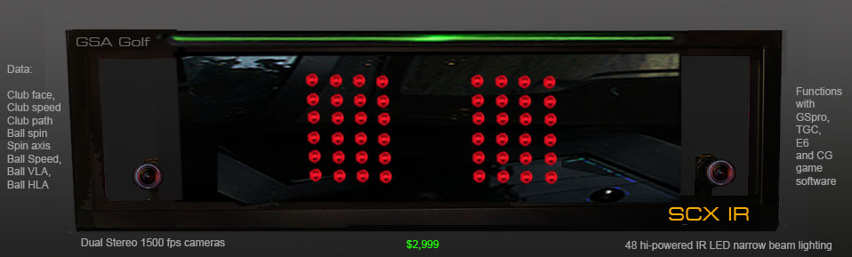
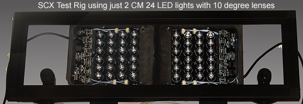
SCX IR Case installation instructions
You will need to purchase 2 CM 24 IR 850 nm lights from CM Vision on Amazon
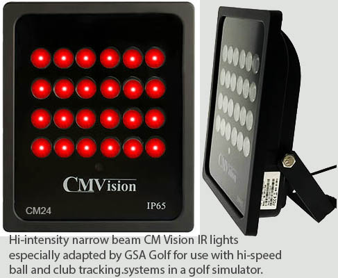
Remove the glass panels and frame (4 screws on each corner on the back),
remove and replace all 24 lenses in each light with narrow beam lenses
In order to adapt the standard CM24 IR light with narrow beam (15 to 25 degree) lenses
you will have to purchase the narrow beam lenses on Amazon,
open up the CM24 (just 4 screws) and replace all wide angle lenses with the new narrow beam lenses.
The old lenses just twist off
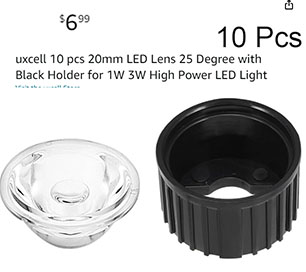
You will require 24 narrow beam lenses per CM24 IR 850nm light for a total of 72 lenses.
Cost on Amazon for the lenses will be around
$70
for the 72 lenses ($7 per pack of 10).
It takes a while to un-twist all the original lenses and replace them all with the new narrow beam lenses
but without this,
the light intensity from the standard CM24 with wide angle lenses won't be sufficient to capture hi-speed frames of the ball and club.
Remove the control box from the SCX case
Remove the red tape from the sticky tape from the back side of the SCX case and adhere the 2 lights as shown above.
Press them down hard and the sticky tape will hold the lights in place.
Refit the control box and connect the lights to it.
Fix your cameras to the left and right camera mounts.

Click above to read more ...
![]()
Technical Support
Email and remote access support is available for all original purchasers of GSA Golf systems.
E-mail support is free of charge for all original purchasers of GSA Golf systems.
Remote access support is available for all purchasers for $75 per session (max 1 hr per session)
Note that your 1 hour session can be divided up to 2 sessions of 30 min or 4 15min sessions
Remote support sessions are available 7 days a week (including weekends i.e. Sat or Sun) at 2pm ET
Remote access support requires that you have "TeamViewer" installed on your PC
Go to www.teamviewer.com to get your free team viewer installed
Buy GSA Golf remote support 1 hr session for
Price: $ 75.00
![]()

![]()
 Home
Home Sensors
 Cameras
 Software
 Enclosures
 GSA Courses
 Installation
 Business